background image

GB

16

6. MAINTENANCE

W

W

W

W

A

A

A

A

R

R

R

R

N

N

N

N

II

II

N

N

N

N

G

G

G

G

!!

!!

!!

!!

!!

!!

THIS PROCEDURE MAY ONLY BE DONE

BY AN AUTHORISED TECNOMAC

INSTALLATION TECHNICIAN

Regular maintenance is limited to descaling or
replacing the boiler, together with annual
cleaning (generally done before seasonal
close-down).

CYLINDER BOILER CLEANING
AND REPLACEMENT

This is necessary when scale on the active sur-
faces of the electrodes prevents the sufficient
passage of electrical current (alarms E08 and
E06).
To dismantle the cylinder boiler:
– drain water completely, by pressing MANUAL

DRAIN button 11) on the control panel;

– cut of power to the equipment by means of

switch or line fuses;

– remove steam pipe from the boiler;
– disconnect wiring to main electrodes and

unplug light level electrodes;

– unscrew fixing knob to free cylinder, lift boiler

to remove. The boiler may generally be used
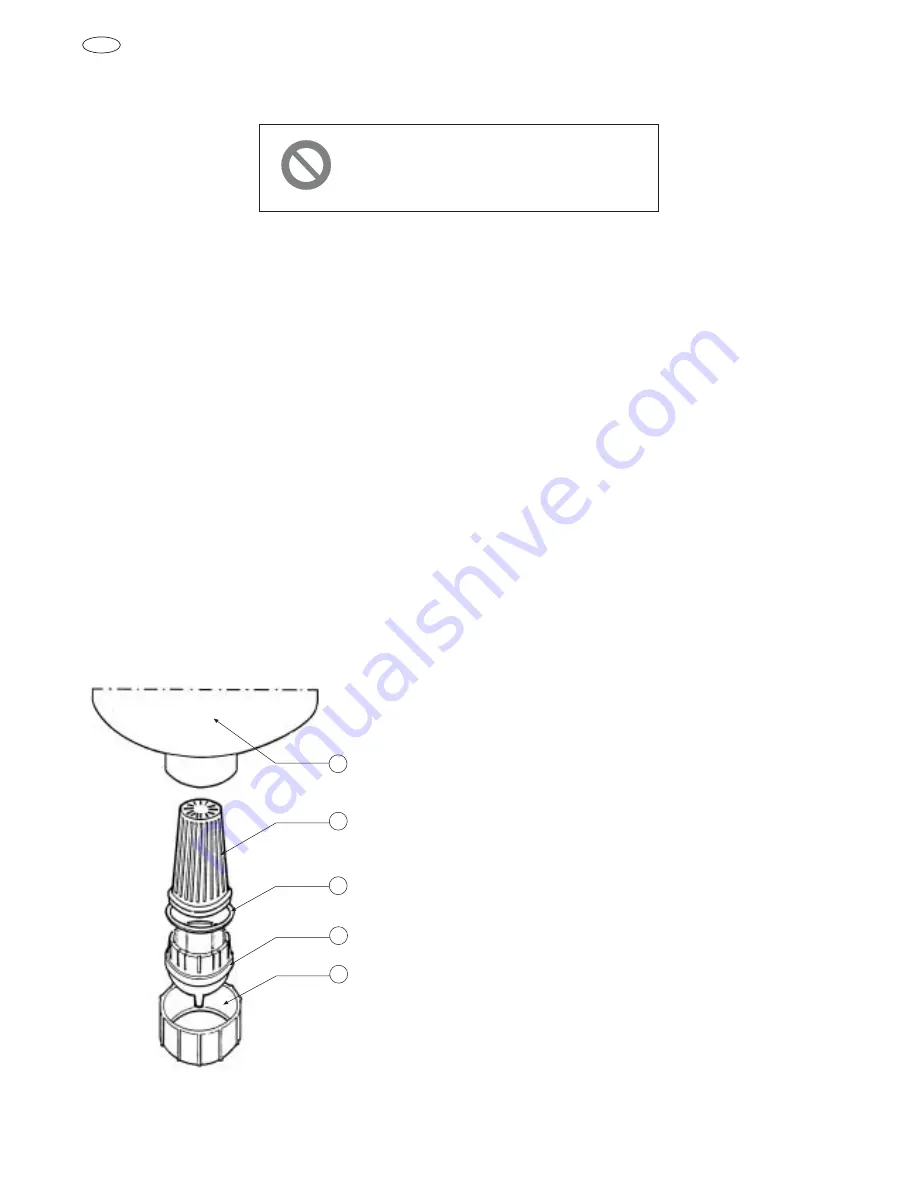
again after descaling. Unscrew ring nut (see
figure) and extract bottom filter. Remove
scale and calcareous deposits under a jet of
water and clean grids mechanically or chem-
ically with a commercially available cleaner.
When electrode wear is such that regenera-
tion is insufficient, the boiler must be
replaced. Exchange only involves the body
of the boiler and the gasket. The ring nut,
connection piece and filer do not deteriorate
with use.

Reassemble the boiler in reserve sequence,
after, checking and if necessary the washer
between the threaded connection and the dis-
charge group.

CLEANING AND SEASONAL
CLOSE-DOWN

Annually, or before summer close-down,
inspect and clean the systems. Drain water
from the boiler by pressing the MANUAL
DRAIN pushbutton 11) on the control panel
and cutting off power.
The following is Recommended:
– dismantle and wash water intake valve, and

check that intake filter is clean;

– dismantle drain group, cleaning conduits and

nozzles and removing and solids from the
base of the syphon;

– inspect water intake, drain, steam and con-

densation pipes, and replace them it they are
worn out or fragile.

5

4

1

3

2

1. RING NUT
2. CONNECTION PIECE
3. GASKET
4. FILTER
5. CYLINDER BOILER

Summary of Contents for T 98 E H4

Page 1: ...Cod 71503313 0 10 2000 OUR SYSTEMS COMPLY WITH EEC DIRECTIVE 73 23 89 336 INSTRUCTION MANUAL S T E A M H U M I D I F I E R S T 98 E H4 GB ...

Page 2: ...ACHINE AND OR COMPONENTS 7 ADJUSTMENT AND SETTING PROCEDURES 8 MACHINE CLEANING AND MAINTENANCE RELATIVE TO THE FOLLOWING PARTS AND COMPONENTS ELECTRICAL ELECTRONIC MECHANICAL COOLING SYSTEM W W W WA A A AR R R RN N N NI I I IN N N NG G G G MACHINE USER IS SEVERELY PROHIBITED FROM CARRYING OUT THE FOLLOWING OPERATIONS AS WELL AS THOSE MARKED WITH THIS SYMBOL ...

Page 3: ... ABSORPTION TYPE OF CONTROL AMPEROMETRIC TRANSFORMER TAM THREE PHASE 1 E400TA 1 24 V50 60 Hz 30 VA CDP 100 Kg h I W Kg h I W Kg h I W K I W 220 V 240 V 380 V 415 V POWER SUPPLY VOLTAGE 8 8 8 5800 8 8 5800 OPERATING TEMPERATURE RANGE C FEED WATER PRESSURE AIR DUCT PRESSURE RESISTANCE CONDUCTIVITY OF FEED WATER 0 40 C 1 10 bar 200 mm H20 800 800Ω 125 1250 µS cm ...

Page 4: ...d allowing water to fill the feed tank from which it descends by the force of gravity to the inside of the cylinder The two small top level electrodes positioned at the top of the cylinder control that the water level does not supersede the maximum value Beyond this maximum value water is dis charged through the overflow pipe of the feed tank The other two electrodes positioned on the feed tank me...

Page 5: ... as shown in figure Some of the indicators are simply displayd val ues while others blink on and off when dis played and are parameters that may be modi fied by the user see section on modifiable functional Iparameters A great number indicators are shown 1 absorbed current 2 desired production Kg h 3 unit configuration visualisation of humidifi er model power supply voltage number of phases nomina...

Page 6: ...ntioned pre alarms do not block the functioning of the unit and they are turned off automatically as soon as the conductivity within the cylinder reaches projected values If the situation persist after numerous fillings particularly when the humidifier has been in use for some time it means that the cylinder needs cleaning or replacement and on addition al alarm E08 will appear blocking the functi...

Page 7: ...n already signalled by a prealarm which does not allow the continua tion of regular steam production eg cylinder exhausted It may appear following a temporary situation voltage excess lack of water etc which requires intervention of personnel The alarm consist of visualisation on the display or eventual trans mission via serial line on the relative code blocking of the humidifying function reset i...

Page 8: ...om filter Remove scale and calcareous deposits under a jet of water and clean grids mechanically or chem ically with a commercially available cleaner When electrode wear is such that regenera tion is insufficient the boiler must be replaced Exchange only involves the body of the boiler and the gasket The ring nut connection piece and filer do not deteriorate with use Reassemble the boiler in reser...

Reviews: