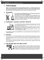
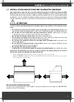
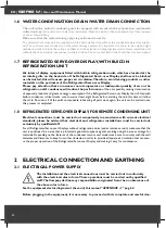
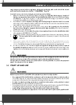
background image

EN | 

SERIE M

 | User and Maintenance Manual

44

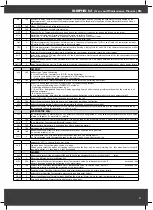
ALARMS

Label

Fault

Cause

Effects

Remedy 

E1

Probe1 faulty

(cold room)

• reading of out of range operating values

• probe faulty / short-circuited / open

• Display label 

E1

• Alarm icon permanently ON

• Min/max alarm regulator disabled

• Compressor operation according to “

Ont

 and “

OFt

” parameters.

• check probe type (NTC)

• check the probe wiring

• replace probe

E2

Probe2 faulty

(defrost)

• reading of out of range operating values

• probe faulty / short-circuited / open

• Display label 

E2

• Alarm icon permanently ON

• The defrost cycle will end due to Time out

 (Parameter “

dEt

”)

• check probe type (NTC)

• check the probe wiring

• replace probe

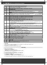
AH1

Probe1 HIGH

Temperature alarm

• value read by Pb1 > HAL after time

 of “

tAO

”. (see “MIN/MAX ALARMS table)

• Registration 

AH1

 label in the AL folder

• No effect on regulation

• Wait until temperature value read by probe1 

returns below HAL.

AL1

Probe1 LOW

Temperature alarm

• value read by Pb1 < LAL after time

 of “

tAO

”. (see “MIN/MAX ALARMS table)

• Registration 

AL1

 label in the AL folder

• No effect on regulation

• Wait until temperature value read by probe1 to 

come back obove LAL

EA

External alarm

• Digital input activated (H11 set as external 

alarm)

• Registration 

EA 

label in the AL folder

• Alarm icon permanently ON

• Regulation blocked if 

EAL

 = y

• check and remove the external cause which 

generate alarm on D.I. 

OPd

Door Open alarm

• Digital input activated (H11 set as door switch)

 (for a longer time than 

tdO

)

• Registration 

Opd

 label in the AL folder

• Alarm icon permanently ON

• Regulator blocked

• close the door

• delay function defined by 

OAO

Ad2

Defrosting

for time-out

• end of defrosting because of time instead of 

because of reaching the defrost end temperature 

detected by the Pb2 probe.

• Registration 

Ad2

 label in the AL folder

• Alarm icon permanently ON

• wait until the next defrost for automatic return 

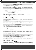
MANUAL DEFROST CYCLE ACTIVATION

To manually activate the defrost cycle, hold down the 

 key for 5 seconds.

If the defrost conditions are not satisfied:

- the parameter OdO ≠ 0 (

EW961, EW971 and EW974

)

- the evaporator probe Pb2 temperature is higher than the defrost end temperature (

EW971 and EW974

) the display will flash 3 times, to indicate 

that the operation will not be carried out.

DIAGNOSTICS

Alarms are always indicated by the buzzer (if present) and the alarm icon  .

To switch off the buzzer, press and release any key, the relative icon will continue to flash

.

NOTES

If alarm exclusion times have been set (see ‘AL’ folder in the parameters table) the alarm will not be signalled

.

A probe 1 (Pb1) malfunction alarm will appear directly on the display with the

indication E1.

Models EW971 and EW974

: A probe 2 (Pb2) malfunction alarm will appear

directly on the display with the indication E2.

DIAGNOSTICS

The instrument is designed for panel mounting. Make a hole of 29x71 mm, insert the instrument and fix it using the brackets provided. Do not 

mount the instrument in humid and/or dirty places; it is suitable for use in ordinary polluted places. Ventilate the place in proximity to the instru

-

ment colling slits.


USING THE COPY CARD

The Copy Card is an accessory connected to the TTL serial port used for quick programming of the device parameters (upload and download a 

parameter map to one or more devices of the same type). Upload (label UL) and copy card formatting (label Fr) operations should be performed 

as explained below:

Summary of Contents for M 1000 VC

Page 1: ...018 Vetrine refrigerate Refrigerated serve over displays Refrig ere mueble Kuehl vitrinen MANUALE D USO E MANUTENZIONE USER AND MAINTENANCE MANUAL MANUEL D INSTALLATION E DE FONCTIONNEMENT BEDIENUNGS...

Page 2: ...uttore oppure da persone esperte Se il cavo di alimentazione danneggiato esso deve essere sostituito dal costruttore o dal suo servizio assistenza tecnica o comunque da una persona con qualifica simil...

Page 3: ...SOSTITUZIONEVETRO FRONTALE LATERALE MENSOLE Pag 15 6 3 SOSTITUZIONE ILLUMINAZIONE Pag 15 6 4 SOSTITUZIONE MOTOVENTILATORE Pag 16 6 5 SOSTITUZIONE COMPRESSORE GAS REFRIGERANTE Pag 16 6 6 MOBILE CON SBR...

Page 4: ...to e o manutentore per compie re in modo corretto e sicuro tutte le operazioni di installazione messa in funzione smontaggio e smaltimento dell apparecchio Questo manuale d uso e manutenzione contiene...

Page 5: ...sono disponibili con 2 finiture differenti VERSIONE BASSO Fiancate coibentate basse fino a terra spessore 40 mm e frontale basso fino a terra VERSIONE ALTO Fiancate coibentate alte da terra spessore...

Page 6: ...ati nella tabella lunghezza peso APPENDICE 5 pag 58 Il produttore declina ogni responsabilit per operazioni logistiche svolte senza ll rispetto delle norme di sicurezza 1 3 IMBALLO Alla consegna verif...

Page 7: ...amento dell unit refrigerante Prestare attenzione in presenza di una pedana posizionata posteriormente al mobile frigorifero verificarne la sua altezza in modo che questa non ostruisca le prese d aria...

Page 8: ...essere collocato al riparo degli agenti atmosferici evitando di utilizzare il sito come deposito di materiali A seconda delle caratteristiche del modello dell unita condensatrice remota si devono ris...

Page 9: ...a del mobile ad una prolunga e o riduttore 2 2 MESSA IN FUNZIONE ED UTILIZZO ATTENZIONE Attenzione prima di effettuare l avviamento accertarsi che non vengano eseguite le operazioni con mani umide o b...

Page 10: ...orcizia Fare attenzione durante le operazioni di pulizia della vasca del mobile frigorifero bisogna porre attenzione a non ferirsi con le alette dell evaporatore che visto il loro spessore ridotto son...

Page 11: ...di sistema automatico per lo sbrinamento periodico giornaliero gi impostato in fabbrica e modificabile in numero durata ed intervallo agendo sul pannello di controllo tale operazione deve essere esegu...

Page 12: ...strettamente necessario al carico dei prodotti Caricando eccessivamente il mobile di prodotto da raffreddare si peggiorano tutte le condizioni di funzionamento rischiando di danneggiare i prodotti gi...

Page 13: ...fero in posizione perfettamente orizzon tale agendo se necessario sulla regolazione dei piedini a vite sulle gambe del banco per regolarne il livello e verificare la planarit con una bolla 1 4 POSIZIO...

Page 14: ...2 sezioni con le viti da A alla C nelle apposite predisposi zioni al fissaggio Unire le plafoniere porta luce rivettando le 2 estremit in lamiera predisposte E Una volta unite le 2 sezioni Rimuovere...

Page 15: ...mobili dotati di pistoni 6 2 SOSTITUZIONEVETRO FRONTALE LATERALE MENSOLE Nel caso di danneggiamento e o sostituzione del vetro frontale vetro laterale lato spalla della vetrina recuperare i frammenti...

Page 16: ...inamento elettrico attenzione a non scottarsi sulla resistenza elettrica che potrebbe risultare ancora calda Aspettare quindi il suo raffreddamento e successivamente iniziare le operazioni di manutenz...

Page 17: ...are dell EUT possibili opzioni C con unit compressore S senza unit compressore N senza unit compressore and without other electric components appliance provide only with internai light expositor unit...

Page 18: ...rilasciare Scorre le voci del menu Decrementa i valori Premere per almeno 5 sec Funzione configurabile dall utente par H32 SET ENTER Premere e rilasciare Visualizza eventuali allarmi se presenti Acce...

Page 19: ...cedura usata per il blocco MENU DI PROGRAMMAZIONE Per entrare nel menu Programmazione premere per oltre 5 secondi il tasto Se previsto verr richiesta una PASSWORD di accesso PA1 vedi paragrafo PASSWOR...

Page 20: ...tempo maggiore di tdO Registrazione label Opd nella cartella AL Icona Allarme fissa Blocco del regolatore chiudere la porta funzione ritardo definita da OAO Ad2 Sbrinamento per time out fine sbriname...

Page 21: ...one eseguita e dLn per operazione fallita DOWNLOAD Copy Card strumento NOTE dopo le operazioni di Download lo strumento funzioner con le impostazioni della nuova mappa appena caricata ALLARME DI TEMPE...

Page 22: ...tronico da incorporare secondo le caratteristiche del funzionamento automatico come dispositivo di comando ad azione di tipo 1 B come dispositivo di classe A in relazione alla classe e struttura del s...

Page 23: ...2 sbrinamento con la modalit Free sbrinamento indipendente dal compressore dit 1 2 defrost interval time Tempo di intervallo fra l inizio di due sbrinamenti successivi dCt 2 defrost Counting type Sele...

Page 24: ...e fino al successivo raggiungimento del valore di Setpoint 2 visualizza la label dEF durante lo sbrinamento e fino al successivo raggiungimento del valore di Setpoint dro 2 display read out Seleziona...

Page 25: ...250 30 min 1 2 dSt 50 0 150 8 0 C F 1 2 dPO n y n n y n flag 2 FPt 0 1 0 flag 2 FSt 50 0 150 50 0 C F 1 2 FAd 1 0 50 0 2 0 C F 2 Fdt 0 250 0 min 1 2 dt 0 250 0 min 1 2 dFd n y y flag 1 2 FCO n y y fl...

Page 26: ...e service When parts are being replaced and when removal of the plug is foreseen and removal of the plug is clearly indicated it must be such that an operator may check from any point to which he has...

Page 27: ...CHECKS Pag 39 6 2 GLASS REPLACEMENT Pag 39 6 3 TOP CANOPY AND SHELVES LIGHTINGS REPLACEMENT Pag 39 6 4 MOTOR FAN REPLACEMENT Pag 40 6 5 COMPRESSOR REFRIGERANT GAS REPLACEMENT Pag 40 6 6 UNIT FITTED W...

Page 28: ...staff so that the same can carry out correctly and securely all the operations of installation implementation commissioning dismantling and disposal of the appliance This user and maintenance manual...

Page 29: ...o the floor 40 mm thick and short front panel down to the floor TALLVERSION Tall insulated side panels from the floor 40 mm thick and tall front panel from the floor The model SERIES M 1000 includes M...

Page 30: ...he unloading positioning and installation procedures of the Re frigerated Serve over Display inside the shop kitchen according to the model of the Refrigerated Serve over Display please read carefully...

Page 31: ...rectly exposed to air from fans vents or fan coil unit air conditioner Do not block or obstruct the air inlets of the built in refrigeration unit Do not place any objects on the unit including boxes o...

Page 32: ...ter energy consumption If the Refrigerated Serve over Display that is fitted with built in condenser is tilted make sure to wait at least eight hours before starting the unit this time will allow the...

Page 33: ...l assistance service or however by a person with similar qualifications so as to avoid all risks No liability whatsoever can be accepted if the above instructions in not complied with 8 In order to pr...

Page 34: ...mpletely powered off Never use high pressure water jet to wash internal parts of the Refrigerated Serve over Display as electrical parts could be damaged Only use warm water with non aggressive deterg...

Page 35: ...ording to local legislation provided that they are under strict supervision by a tutor and are adults as mentioned above In other words trainees must be in normal physical and psychological condition...

Page 36: ...he following when the doors are opened cold air is released and therefore it is advisable to limit opening the doors and only do so for the time required to load products Storing non frozen products w...

Page 37: ...frigorifero in posizione perfettamente orizzon tale agendo se necessario sulla regolazione dei piedini a vite sulle gambe del banco per regolarne il livello e verificare la planarit con una bolla 1 4...

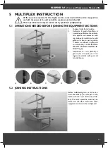
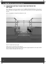
Page 38: ...e cabinet closer together fix the 2 sections with the screws from A to C in the appropriate fixing positions Join the canopy lights by riveting the presetted joints on it E Once the 2 sections have be...

Page 39: ...rectly clean the condenser of the refrigeration unit 6 2 GLASS REPLACEMENT In case of replacement or damage of the front of glass side glass shelf glass do not dissipate them on the environment Glass...

Page 40: ...open the circuit breaker upstream of the connection of the Refrigerator unit Then replace ATTENTION In the equipments with electric defrosting system pay attention to the electrical heating element t...

Page 41: ...0140 length 140 cm 0150 length 150 cm 0180 length 180 cm 0182 length 182 cm 0200 length 200 cm 0240 length 240 cm 0250 length 250 cm 0262 length 262 cm 0280 length 280 cm 0300 length 300 cm 0350 lengt...

Page 42: ...d release Displays alarms if active Opens the Machine Status menu Press for at least 5 secs Opens the Programming menu Confirms commands SET Reduced SET LED Flashing reduced set active Quick flashing...

Page 43: ...To access the Programming menu press for at least 5 secs the key If specified the PA1 access PASSWORD will be requested see PASSWORD paragraph At the access the display will show the first parameter d...

Page 44: ...eachingthedefrostendtemperature detectedbythePb2probe RegistrationAd2labelintheALfolder AlarmiconpermanentlyON waituntilthenextdefrostforautomaticreturn MANUAL DEFROST CYCLE ACTIVATION To manually act...

Page 45: ...ention Never work on electrical connections when the machine is switched on The device is equipped with screw or removable terminals for connecting electric cables with a diameter of 2 5mm2 one wire p...

Page 46: ...meter of 2 5mm2 Connectors TTL for connection to Copy Card Temperature Operating 5 55 C Storage 30 85 C Humidity Operating Storage 10 90 RH not condensing Electrical Caracteristics Power Supply 230Vac...

Page 47: ...s on and start everytime the instrument switch on 2 compressor stop Each time the compressor stops a defrosting cycle is performed according to parameter dtY dOH 2 defrost Offset Hour Start of defrost...

Page 48: ...TE the switch between C and F DO NOT modify setpoint differential etc for example set 10 C become 10 F ddd 2 Selection of type of value to be displayed 0 Setpoint 1 cold room probe Pb1 2 evaporator pr...

Page 49: ...0 30 min 1 2 dSt 50 0 150 8 0 C F 1 2 dPO n y n n y n flag 2 FPt 0 1 0 flag 2 FSt 50 0 150 50 0 C F 1 2 FAd 1 0 50 0 2 0 C F 2 Fdt 0 250 0 min 1 2 dt 0 250 0 min 1 2 dFd n y y flag 1 2 FCO n y y flag...

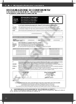
Page 50: ...CONFORMITY DECLARATION DE CONFORMIT KONFORMIT TSERKL RUNG FARE RIFERIMENTO ALLA DICHIARAZIONE CE CHE ACCOMPAGNA IL PRODOTTO REFERTO CE DECLARATION ACCOMPANYINGTHE PRODUCT REPORTEZ VOUS LA D CLARATION...

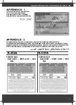
Page 51: ...CARICA GAS GAS LOAD kg CARICA GAS GAS LOAD kg GWP 3 985 GWP 2 141 CO2 CO2 x x APPENDICE 2 ATTREZZATURA CON GAS FLUORURATI AD EFFETTO SERRA EQUIPMENT WITH FLUORINATED GREENHOUSE GASES QUIPEMENT AVEC GA...

Page 52: ...nella prossima pagina The plate defines all the technical data of the Refrigerated Serve over Display as showed on the table in the next page L tiquette d finit toutes les donnes techniques sur le pro...

Page 53: ...Kosten Cantidad de refrigerante 10 Pot elettrica illuminazione Watt top lighting total Electrical power Puissance total de la lumi re Elektrische Leistung von licht Potencia electrica de iluminacion...

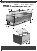
Page 54: ...e manutenzione 54 9 10 11 1 1 7 6 5 8 2 2 3 3 3 3 4 SERIE M 800 900 1000 APPENDICE 4 DESCRIZIONE PARTI DEL MOBILE FRIGORIFERO CLOSE MULTIDECK DISPLAY PARTS DESCRIPTION DESCRIPTION DU MEUBLE FRIGO BES...

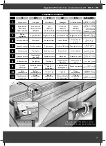
Page 55: ...terung Soporte delantero 6 Vetro frontale Front glass Fa ade en verre Frontscheibe Vidrio frontal 7 Mensola in vetro Intermediary glass shelf Tablette en verre Glasboden Estante de cristal 8 Plafonier...

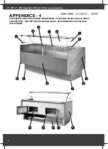
Page 56: ...e manutenzione 56 9 12 12 10 11 5 1 7 6 5 5 8 2 2 3 3 3 4 APPENDICE 4 DESCRIZIONE PARTI DEL MOBILE FRIGORIFERO CLOSE MULTIDECK DISPLAY PARTS DESCRIPTION DESCRIPTION DU MEUBLE FRIGO BESCHREIBUNG DERTEI...

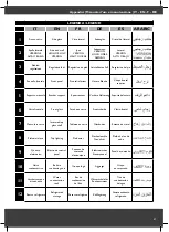
Page 57: ...avant Vordere Halterung Soporte delantero 6 Vetro frontale Front glass Fa ade en verre Frontscheibe Vidrio frontal 7 Mensola in vetro Intermediary glass shelf Tablette en verre Glasboden Estante de cr...

Page 58: ...at In der Phase von Auftauen W A 1050 4 4 1320 5 5 1610 6 7 2060 8 5 2190 9 1 2800 11 6 2800 11 6 3340 13 9 4120 17 2 Potenza assorbita dall illuminazione dotazione standard Power absorbed by lighting...

Page 59: ...rage Erforderliche Gesamtleistung Standardausstattung ohne aggregat In der Phase von Auftauen W A 1050 4 4 1320 5 5 1610 6 7 2060 8 5 2190 9 1 2800 11 6 2800 11 6 3340 13 9 4120 17 2 Potenza assorbita...

Page 60: ...d givrage Erforderliche Gesamtleistung Standardausstattung ohne aggregat In der Phase von Auftauen W A 1050 4 4 1320 5 5 1610 6 7 2060 8 5 2190 9 1 2800 11 6 2800 11 6 3340 13 9 4120 17 2 Potenza asso...

Page 61: ...age Erforderliche Gesamtleistung Standardausstattung ohne aggregat In der Phase von Auftauen W A 1050 4 4 1320 5 5 1610 6 7 2060 8 5 2190 9 1 2800 11 6 2800 11 6 3340 13 9 4120 17 2 Potenza assorbita...

Page 62: ...porato dotazione standard In fase di sbrinamento Total absorbed power built in unit standard version In defrosting phase Puissance absorb e totale groupe log quipement standard en phase ded givrage Er...

Page 63: ...porato dotazione standard In fase di sbrinamento Total absorbed power built in unit standard version In defrosting phase Puissance absorb e totale groupe log quipement standard en phase ded givrage Er...

Page 64: ...3 502 FAX 39 0 049 8873 665 Tipologia Tipology SIMPLE DEFROSTING www dgdsrl it info dgdsrl it 11 4 12 Prodotto Product Pasticceria Pastry SCHEMA ELETTRICO ELECTRICAL DIAGRAM ELECTRIQUE SCHEMA 230V 1P...

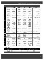
Page 65: ...NTOLE BANCO FANS CABINET 8 RESISTENZA ANTIAPPANNANTE ANTIDEMISTER HEATER SONDA TEMPERATURA TEMPERATURE PROBE 1 ALIMENTAZIONE ELETTRICA 230V ELECTRICAL POWER SUPPLY 230V Legenda Legend 5A REATTORI LAMP...

Page 66: ...IT EN F DE ARABIC Manuale d uso e manutenzione 66 Note...

Page 67: ...Manuale d uso e manutenzione IT EN F DE ARABIC 67 Note...

Page 68: ...o not commit the Manufacturer Only the information indicated on the order confirmation are binding and counts as a proof Les images du produit ont t r alis e au moment de l impression du catalogue et...

Reviews: