6
STEP 7
CHARGE
State Of
Charge:
50% - 75%
LED #4 : BLUE
1
2.
8V
16
V
B
M S rese
t
16V
24-7
24-7
Bms
Bms
12.8V
12.8V
LFP
LiFePO
4
1234
12345
16V
/oml12.8v16v
optimate1.com
/oml12.8v16v
5
4
3
1a 1b
2
8
6
7
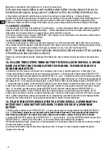
The
ampmatic
™ CHARGE program automatically determines
the most efficient rate of charge current for the connected battery,
according to its state of charge, state of health, and electrical storage
(Ah) capacity. The delivered current may be anywhere from 2.5A to
9.5A
(16V:
7.5A
)
(within normal
safeTº
temperatures, see page 5)
.
For batteries with an electrical storage (Ah) capacity less than 10Ah
charge current is automatically adjusted lower to an average equal
to battery Ah capacity, e.g. a 2.5Ah / 2500mAh battery receive an
average of 2.5 Amps.
NOTE:
For safety reasons there is an overall charge time limit of 24
hours up to STEP 7.
STEP 8
OPTIMIZE
cell
balancing
State Of
Charge:
75% - 100%
LED #5 : BLUE
1
2.
8V
16
V
B
M S rese
t
16V
24-7
24-7
Bms
Bms
12.8V
12.8V
LFP
LiFePO
4
1234
12345
16V
/oml12.8v16v
optimate1.com
/oml12.8v16v
5
4
3
1a 1b
2
8
6
7
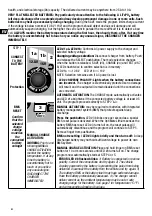
This final charge mode starts when the voltage has reached 14.4V
(16V:
18V
)
for the first time during STEP 7.
The
ampmatic
™ current control program now delivers pulses of
current to equalise the individual cells within the battery and optimizes
charge level.
Minimum charge time is influenced by initial State Of Charge as
measured during STEP 3, varying between 10 minutes for a battery
with 80% or higher state of charge to the maximum of 120 minutes for
a battery with 40% or less.
STEP 9
State Of
Charge
TEST
LED #6 : GREEN
1
2.
8V
16
V
B
M S rese
t
16V
24-7
24-7
Bms
Bms
12.8V
12.8V
LFP
LiFePO
4
1234
12345
16V
/oml12.8v16v
optimate1.com
/oml12.8v16v
5
4
3
1a 1b
2
8
6
7
TEST after charge : Delivery of current to the battery is interrupted
for 30 minutes** to allow the program to determine the battery’s
ability to retain charge.
**
IF charging started in SAVE mode (LED #3) the voltage retention
test is extended to 12 hours to confirm battery health.
LED #6 (green) will remain on for batteries able to hold 90% or
higher state of charge (SOC%),
otherwise the TEST result is adjusted
lower (LED #7, LED #8) in real time according to the measured battery
voltage. Consult the table on page 2 to match TEST LED indication to
an estimated state of charge percentage (SOC%).
Also read section “NOTES ON TEST RESULTS” below.
STEP 10
OptiMATE
24-7
Maintain
LED #6 / 7 / 8
1
2.
8V
16
V
B
M S rese
t
16V
24-7
24-7
Bms
Bms
12.8V
12.8V
LFP
LiFePO
4
1234
12345
16V
/oml12.8v16v
optimate1.com
/oml12.8v16v
5
4
3
1a 1b
2
8
6
7
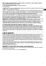
MAINTENANCE CHARGE: LED #6 / 7 / 8 steady on
according to final voltage measured at termination of STEP 9.
The
MAINTENANCE CHARGE CYCLE
consists of 30 minute charge
periods followed by and alternating with a 30 minute ‘rest’ periods,
during which there is no charge current.
During the
30 minute*
charge cycles current is delivered only if the
battery has lost charge.
*
The charge cycle may be extended if high current draw is sensed and
will continue until current demand once again reduces below 1A.
The
BATTERY REFRESH CYCLE
is performed if the charger detects the
battery has suddenly lost significant charge. The program reverts to
STEP 8 (LED #5) before returning to STEP 9 and STEP 10 .
Read section MAINTAINING A LITHIUM BATTERY FOR EXTENDED
PERIODS.
NOTES ON TEST RESULTS:
The voltage of a cooled battery is directly proportional to its State Of Charge
percentage (SOC%). Immediately following charging a battery may briefly hold a higher voltage, as charging
raises the temperature of chemical elements within the battery. A battery recovered from a deep discharged
state may need longer to cool and voltage to settle and reflect its true state of charge (SOC%).
1.
For any test result other than green #6, disconnect the battery from the electrical system it supports, and
reconnect the OptiMate Lithium. If a better test result is now obtained, this suggests that the power losses are
partly due to an electrical problem in the electrical system and not in the battery itself.


