background image

8

Connecting a Cassette Deck

Use audio/video cables (not supplied) to connect a cassette 

deck to the receiver. Connect red plugs to the right 

AUDIO


jacks and white plugs to the left 

AUDIO

 jacks. Make sure you 

connect the cassette deck to both the 

TAPE


IN

 and 

TAPE


OUT


sets of jacks.

N

N

N

Nooootttteeee:::: If the cassette deck is placed too close to the receiver, 

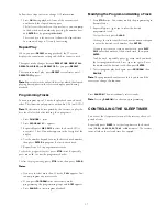
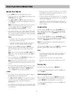
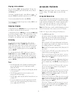
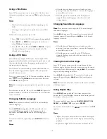
noise might occur during cassette playback. If this happens, 

move the cassette deck farther away from the receiver.

Connecting a VCR

Use audio/video cables (not supplied) to connect a VCR to the 

receiver. Connect red plugs to the right 

AUDIO

 jacks and white 

plugs to the left 

AUDIO

 jacks.

Connect yellow plugs to the 

VIDEO

 jacks.

N

N

N

Nooootttteeee: : : : Make sure you connect the VCR to both the 

IN

 and 

OUT


sets of jacks.

Connecting a Satellite Receiver or Cable Box

Use audio/video cables (not supplied) to connect a satellite 

receiver or cable box to the receiver. Connect the yellow plug 

to the 

VIDEO

 jack.

If your satellite receiver or cable box has analog audio connections

connect red plugs to the right 

AUDIO

 jacks and white plugs to 

the left 

AUDIO

 jacks. To use your satellite receiver (or cable 

box), select the SAT function (see “Using a Satellite Receiver or 

Cable Box” on Page 12).

If your satellite receiver or cable box has digital audio output

, use 

an optical cable to connect the satellite receiver to the home 

theater receiver’s 

SAT IN

 optical jack. To use your satellite 

receiver or cable box, select the SAT-OPT function (see “Using 

a Satellite Receiver or Cable Box” on Page 12).

N

N

N

Nooootttteeee:::: Your cable box or satellite receiver must use audio/video 

cables or Toslink optical cable to connect to the receiver. If 

your equipment only uses coaxial cable, you cannot connect it 

to the receiver.

Connecting a Digital (Optical) Audio 
Component

You can connect a digital audio Component such as an  

MD (Mini Disc) or DAT (Digital AudioTape) recorder to the 

receiver’s 

DIGITAL OUT

 to record audio from the receiver.

Use Toslink optical cable to connect the MD or DAT recorder 

to the receiver’s 

DIGITAL OUT

 optical jack.

You can also connect a satellite receiver, portable CD player, 

MD or DAT recorder, or other components with digital output 

to the receiver’s 

SAT IN 

optical jack. Use Toslink optical cable 

to connect the desired Component to the receiver.

Connecting an Auxiliary Audio Component

You can also connect an audio Component that does not require 

a Toslink Optical cable (such as an MP3 player, playback cassette  

deck, or portable CD player) to the Home Theater Audio System.  

Use audio cables to connect the desired Component to the receiver’s 

AUX

jacks. Connect red plugs to the right 

AUDIO

 jacks and white 

plugs to the left 

AUDIO

 jacks.

Connecting a Sub Woofer

You can connect a powered subwoofer to the system.  

Connect the sub woofer to the receiver’s 

SUB WOOFER PRE-OUT 

 jack using shielded audio cable (not supplied).

CONNECTING ANTENNAS

When connecting equipment, always make sure the power is 

switched off and the power cord is disconnected from the wall 

outlet.

FM Indoor Antenna

In an area with strong FM signals, the T-type FM antenna 

(supplied) is sufficient. 

1. Use a flat or Phillips screwdriver to loosen the screws on 

the supplied transformer.

2. Place the metal connectors on the end of theT-type 

antenna’s base on the transformer’s metal contacts 

(underneath the screw heads) then tighten the screws.

3. Plug the transformer into 

ANTENNA FM


75 

..

4. Extend the T-antenna’s other two wires and attach them to 

a wall or window frame for the best possible reception.

N

N

N

Nooootttteeee:::: If you have a FM antenna that uses coaxial cable, connect 

it directly to 

ANTENNA FM


75 

..

FM Outdoor Antenna

In an area where FM signals are weak, you must use a 75-ohm 

unbalanced-type outdoor FM antenna (not supplied). 

Generally, a 3-element antenna will be sufficient. If you live in 

an area where the FM signals are particularly weak, it may be 

necessary to use one with 5 or more elements. 

If you have a FM antenna that uses coaxial cable

, connect it 

directly to 

ANTENNA FM


75 

.. 

If you have a twin-lead FM antenna

, connect it to the supplied 

transformer, then plug the transformer into 

ANTENNA FM


75 

(see Steps 1–3 of “FM Indoor Antenna”).

AM Indoor Loop Antenna

The supplied high-performance AM loop antenna is sufficient 

for good reception in most areas. 

Summary of Contents for DVR98

Page 1: ...omplete owner s manual However we recommend you take time to read the owner s manual com pletely to learn about all of the features and operating instructions for the DVR98 The Quick Guide covers only...

Page 2: ......

Page 3: ...UT SAT IN ANTENNA OUT COMPONENT VIDEO IN ANTENNA IN VIDEO IN S VIDEO IN AUDIO OUT OPTICAL AUDIO IN Cr Cb Y V I D E O O U T C O M P O N E N T VIDEO OUT VIDEO IN AUDIO IN AUDIO OUT R VIDEO OUT OPTICAL A...

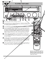
Page 4: ...y one step To adjust the volume use the VOLUME knob on the front of the DVR98 or the VOLUME buttons on the remote IMPORTANT NOTE All radio stations are broadcast in mono or 2 channel stereo so it is r...

Page 5: ......

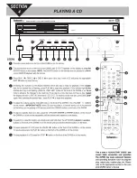
Page 6: ...C scrolls across the display NOTE Please refer to SELECTING DIGITAL AUDIO OUT section of the complete DVR98 owner s manual if the DVD you want to play has the DTS logo on it A flashing disc indicator...

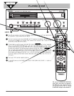
Page 7: ...eatedly until PRO LOGIC scrolls across the display or press the SURROUND button on the remote repeatedly until PRO LOGIC scrolls across the display If the VHS tape does not have the DOLBY PRO LOGIC l...

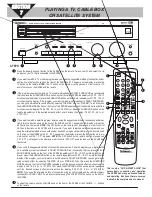
Page 8: ...rogram and you used the suggested method of connection under sec tion 2 turn the function knob on the front of the DVR98 until SAT appears on the display or press the SAT button on the remote NOTE The...

Page 9: ......

Page 10: ...ser s authority to operate the equipment REGION MANAGEMENT INFORMATION Region Management Information This DVD Player is designed and manufactured to respond to the Region Management Information that i...

Page 11: ...erating instructions 2 Cleaning Unplug this product from the wall outlet before cleaning Use only a damp cloth for cleaning Do not use liquid or aerosol cleaners 3 Attachments Do not use attachments a...

Page 12: ...llen into the product If the product has been exposed to rain or water If the product does not operate normally by following the operating instructions Adjust only those controls that are covered by t...

Page 13: ...annel Level 14 Changing the Speaker Distance 14 Surround Effects 15 Changing System Settings Special Circumstances 15 Using the Remote Control to Control Additional Components 15 Controlling the Tuner...

Page 14: ...a true surround sound experience A A A Add dd dd ddi i i it t t ti i i io o o on n n na a a al l l l C C C Co o o om m m mp p p po o o on n n ne e e en n n nt t t t C C C Co o o on n n nn n n nec ec...

Page 15: ...se the color coded wires supplied to connect each speaker to the appropriate terminal Note Be sure to connect the black wires to the black terminals and the red wires to the red terminals DIGITAL OUT...

Page 16: ...receiver s DIGITAL OUT optical jack You can also connect a satellite receiver portable CD player MD or DAT recorder or other components with digital output to the receiver s SAT IN optical jack Use To...

Page 17: ...tances from the TV 2 Install the center speaker above or below the TV so the center channel s sound is localized at the TV screen C C C Ca a a au u u ut t t ti i i io o o on n n n If you choose to ins...

Page 18: ...in tuner mode SKIP SCAN SLEEP Repeatedly press to set the sleep timer DISC 1 2 3 Press to open or close the disc trays Note You cannot use these but tons in tuner mode DIMMER Press once to dim the di...

Page 19: ...memory number in which a station is stored the old station is cleared To store stations on the other band repeat Steps 1 6 substituting the other band in Step 1 N N N No o o ot t t te e e e If you wan...

Page 20: ...ayback press STOP The disc icon stops rotating and appears To resume playback pressPLAY RESUME To stop playback completely press STOP again Continuous Play When the receiver finishes playing an audio...

Page 21: ...ODE selects and deselects pre set mode PRESET During AM or FM reception you can scan through other frequencies or se lect the preset numbers MUTE MUTE Press to immediately stifle the sound level appea...

Page 22: ...kers until the sound evens out Follow these steps to change the channel level 1 Press SETUP CH LEVEL then appears 2 Press FL LEVEL appears 3 Press again F 0dB appears To change the front left speaker...

Page 23: ...or TV is set Mute Volume is operatable for TV only Note1 Note2 To turn on or off the receiver when you select the VCR SAT or TV function press POWER twice C C C Ca a a au u u ut t t ti i i io o o on n...

Page 24: ...m m mp p p po o o or r r rt t t ta a a an n n nt t t t You can only use audio CDs with the reciever CD ROM CD G photo CD and CD i discs can not be played on this player 1 Press POWER The last selected...

Page 25: ...first desired track 5 Repeat Steps 2 4 to program more tracks To check the programmed order press STOP twice Repeatedly press or to view the programmed order To clear the programming press STOP twice...

Page 26: ...playback Doing so might damage the disc and the receiver Use DISC 1 DISC 2 or DISC 3 on the main unit to open or close the disc trays Do not push the disc tray while it is moving Doing so may cause t...

Page 27: ...creen does not change The displays appear on your television screen Using GUI Menu Icons GUI menu icons show disc information for example title or chapter number elapsed playing time audio subtitle la...

Page 28: ...and select N N N No o o ot t t te e e es s s s When the desired language is not selected even after pressing the button several times it means the language is not available on the disc When the power...

Page 29: ...locked unless you enter the correct password again For example if you change the level to 5 the DVD player will not play discs with ratings of 6 7 or 8 unless the correct password is entered from the...

Page 30: ...ER to select the desired output PCM or BITSTREAM then press ENTER BITSTREAM Select BITSTREAMif you have an amplifier or other equipment with DTS decoder or Dolby Digital decoder connected to the recei...

Page 31: ...e DVD display is lit An unplayable disc is inserted Insert a playable disc Check the disc type color system and regional code The disc is placed upside down Place the disc with the playback side down...

Page 32: ...ay is dark or off The dimmer is on Press DIMMER repeatedly to return to the default setting When listening to the music in stereo left right speakers sounds are reversed Speakers are connected wrong A...

Page 33: ...LE 104 106 108 CELEBRITY 102 CITIZEN 104 106 108 138 205 271 COLORTYME 104 106 CONCERTO 104 106 CONTEC CONY 112 113 138 CRAIG 138 CROWN 138 271 CURTIS MATHES 104 106 115 185 205 262 271 CXC 138 DAEWOO...

Page 34: ...105 106 107 110 119 120 121 135 156 185 198 199 200 201 202 210 221 279 281 287 290 SAMPO 104 106 271 272 SAMSUNG 104 105 106 112 115 119 204 205 206 271 272 SAMSUX 271 Brand Codes SANYO 104 109 148...

Page 35: ...8 459 460 507 518 JCI 421 JENSEN 455 456 511 JVC 409 410 411 418 420 421 458 462 468 477 511 523 Brand Codes KENWOOD 409 410 411 416 418 456 511 523 KLH 461 KODAK 414 421 LG GOLDSTAR 409 414 418 454 5...

Page 36: ...S 421 409 TEKNIKA 414 421 426 TMK 413 TOSHIBA 415 449 451 455 465 493 506 516 TOTEVSION 413 414 UNITECH 413 VECTOR RESEARCH 409 410 415 416 513 Brand Codes VIDEOSONIC 413 WARDS 413 414 415 421 423 426...

Page 37: ...718 TANDY 740 TELEVIEW 714 TOCOM 704 723 741 TOSHIBA 726 TSUA 718 TV86 727 UNIKA 708 709 711 UNITED ARTISTS 702 UNITED CABLE 753 713 UNIVERSAL 708 709 710 711 VIDEOWAY 744 VIEWSTAR 715 725 727 740 ZE...

Page 38: ...f model or serial number was removed altered replaced or rendered illegible Warranty does not apply if equipment was modified or serviced by anyone other than an authorized Welton Sound Systems Servic...

Page 39: ...WELTON SOUND SYSTEMS U S A 11625 Columbia Center Drive Suite 100 Dallas Texas 75229 972 243 5602 FAX 972 243 5958 weltonusa com...

Reviews: