Techpro TRIDVR-EL16M4 Users Manual And Important Safety Information Download Page 183


376 


Figure 5-10 


Section 6: From the left to the right ,you can see video quality/fluency/ full 

screen/1-window/4-window/6-window/8-window/9-window/13-window/16-window/20-

window/25-window/36-window.. You can set video fluency and real-time feature 

priority.   


Section 7: PTZ operation panel. Please refer to chapter 5.5 for detailed information.   


Section 8: Image setup and alarm setup. Please refer to chapter 5.6 for detailed 

information.   


Section 9

From left to right, it is to set video quality, video latency, full screen, 

1-window, 4-window.     


Section 10

Zero-channel encoding. This function allows you to view several-channel 

in one window. It supports 1/4-channel mode. Please go to chapter 4.11.5.2.4 to 

enable zero-channel encoding function first.   

5.4


Real-time Monitor 

  In section 2, left click the channel name you want to view, you can see the corresponding 

video in current window.   

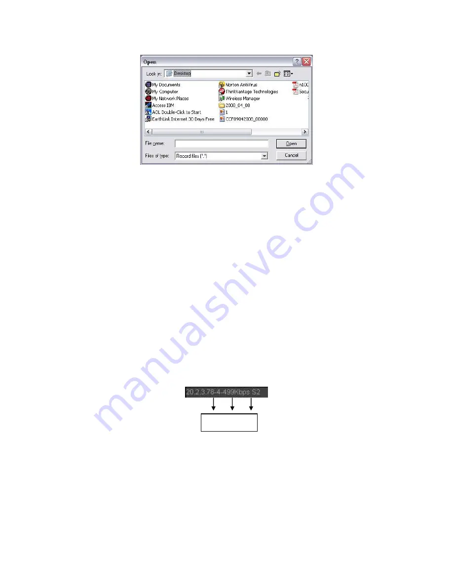
On the top left corner, you can view device IP, channel number, network monitor bit stream. 

See Figure 5-11. 


Figure 5-11 

On the top right corer, there are six unction buttons. See Figure 5-12. 


    1      2        3 

Summary of Contents for TRIDVR-EL16M4

Page 1: ...Elite Series Tribrid User s Manual TRIDVR EL16M4...

Page 2: ...D SPECIFICATIONS 1 1 Overview 1 2 Features 1 3 Specifications 2 OVERVIEW AND CONTROLS 2 1 Front Panel 2 2 Rear Panel 2 3 Connection Sample 2 4 Remote Control 2 5 Mouse Control 2 6 Virtual Keyboard Fro...

Page 3: ...ply 3 5 Connecting Video Input and Output Devices 3 5 1 Connecting Video Input 3 5 2 Connecting Video Output 3 6 Connecting Audio Input Output Bidirectional Audio 3 6 1 Audio Input 3 6 2 Audio Output2...

Page 4: ...tartup Wizard 4 4 Live Viewing 4 5 Right Click Menu 4 5 1 Window Switch 4 5 2 Previous Screen Next Screen 4 5 3 PTZ Control 4 5 4 Auto Focus 4 5 5 Color 4 5 6 Display 4 5 7 Face Search 4 5 8 Search 4...

Page 5: ...anager 4 7 USB Device Auto Pop up 4 8 Main Menu 4 9 Operation 4 9 1 Search 4 9 2 Human Face Search 4 9 3 Backup 4 9 4 Shut Down 4 10 Information 4 10 1 System Info 4 10 2 Event 4 10 3 Network 4 10 4 L...

Page 6: ...utput 5 7 WAN Login 5 8 Setup 5 8 1 Camera 5 8 2 Network 5 8 3 Event 5 8 4 Storage 5 8 5 Setting 5 9 Information 5 9 1 Version 5 9 2 Log 5 9 3 Online User 5 9 4 HDD 5 10 Playback 5 10 1 Search Record...

Page 7: ...KUP DEVICES Appendix B 1 Compatible USB list Appendix B 2 Compatible SD Card list Appendix B 3 Compatible Portable HDD list Appendix B 4 Compatible USB DVD List Appendix B 5 Compatible SATA DVD List A...

Page 8: ...x APPENDIX F COMPATIBLE WIRELESS MOUSE LIST APPENDIX G EARTHING...

Page 9: ...be a reference tool for the installation and operation of your system Here you can find information about this series standalone DVR features and functions as well as a detailed menu tree Before inst...

Page 10: ...rk should be done by the qualified service engineers We are not liable for any problems caused by unauthorized modifications or attempted repair 5 Environment The DVR should be installed in a cool dry...

Page 11: ...the security network to realize strong network and remote monitor function This series product can be widely used in various areas such as banking telecommunication electric power interrogation transp...

Page 12: ...trol The alarm input port and output has the protection circuit to guarantee device safety Communication port RS485 port can realize alarm input and PTZ control RS232 port can connect to keyboard to r...

Page 13: ...andard G 711A G 711U PCM Audio Sampling Rate 8KHz 16Bit Audio Bit Rate 64Kbps Video Port Analog Video Input port 4 ch BNC HDCVI CVBS port 8 ch BNC HDCVI CVBS port 16 ch BNC HDCVI CVBS Network Video In...

Page 14: ...16 channel Backup Mode HDD burner USB device network backup Alarm Alarm Input N A Alarm Output N A HDD HDD Port 2 SATA ports One HDD Space 8T Communication Port Network 1 RJ45 port 1000Mbps Ethernet p...

Page 15: ...information Icon Name Function STATUS Status indicator light The blue light is on when the device is working properly HDD HDD status indicator light The blue light is on when the HDD is malfunction N...

Page 16: ...output port Connect to sound box and etc to output audio signal 9 A RS485 communicatio n port RS485_A port It is the cable A You can connect to the control devices such as speed dome PTZ B RS485_B It...

Page 17: ...204 2 3 5 1U Series Please refer to the following figure for detailed information 2 3 Connection Sample...

Page 18: ...mode playback the next video 6 Previous record In playback mode playback the previous video 7 Play Pause In pause mode click this button to realize normal playback In normal playback click this butto...

Page 19: ...rol the playback process bar Aux function such as switch the PTZ menu 12 Enter menu key go to default button go to the menu 13 Multiple window switch Switch between multiple window and one window 14 F...

Page 20: ...nput a backspace icon and stands for deleting the previous character In numeral input mode _ stands for clear and stands for deleting the previous numeral When input special sign you can click corresp...

Page 21: ...ms in the check box Page up or page down Move mouse Select current control or move control Drag mouse Select motion detection zone Select privacy mask zone 2 6 Virtual Keyboard Front Panel 2 6 1 Virtu...

Page 22: ...s during transportation Then you can open the box to check the accessories Please check the items in accordance with the list Finally you can remove the protective film of the DVR Note Remote control...

Page 23: ...n connect the HDD data cable and the power cable first and then fix the HDD in the device Please pay attention to the front cover It adopts the vertical sliding design You need to push the clip first...

Page 24: ...l operation of the camera Guarantee stability and reliability of the transmission lineBTTTB Please use high quality sound shielded BNC Please select suitable BNC model according to the transmission di...

Page 25: ...erty Reduce the volume of the sound box Using more sound absorbing materials in decoration can reduce voice echo and improve acoustics environment Adjust the layout to reduce happening of the squeakin...

Page 26: ...Details Important Please refer to the specifications for the alarm input and output channel amount Do not merely count the alarm input and out channel amount according to the ports on the rear panel F...

Page 27: ...lel connect the Ground of the DVR and the ground of the alarm detector Please connect the NC port of the alarm sensor to the DVR alarm input ALARM Use the same ground with that of DVR if you use exter...

Page 28: ...to the PTZ device RS485 is a single direction protocol the PTZ device can t return any data to the unit To enable the operation connect the PTZ device to the RS485 A B input on the DVR Since RS485 is...

Page 29: ...not unplug the power cable or click power on off button to shutdown device directly when device is running especially when it is recording There are three ways for you to log out a Main menu RECOMMEND...

Page 30: ...put again to set a password You can set security questions here to reset the password in case you forgot System supports customized setup Please note you need to set two security questions at the same...

Page 31: ...r 4 2 1 to reset the password In login interface click See Figure 4 3 Figure 4 3 System pops up the following dialogue box please answer the security questions and then input the new password twice Se...

Page 32: ...Step button system goes to login interface See Figure 4 6 System consists of three accounts Username admin Password admin administrator local and network Username 888888 Password 888888 administrator...

Page 33: ...OK button System goes to the startup wizard When there are all analog channels the startup wizard includes general encode schedule record control network P2P When there is an IP channel the startup w...

Page 34: ...apter 4 10 3 Figure 4 8 Click Next button you can set P2P function Scan the QR code download the App to the cellphone you can use the smart phone to add the device See Figure 4 9 For detailed informat...

Page 35: ...1 1 Please note you can not see the following interface if there is no digital channel You can go to Main menu Setting Camera Channel type to set IP channel first Please refer to chapter 4 11 1 3 5 f...

Page 36: ...229 Figure 4 11 Click Next button you can go to Schedule interface See Figure 4 12 For detailed information please refer to chapter 4 11 4 1 Figure 4 12...

Page 37: ...ou can left click mouse in the channel 1 and then drag to channel 2 release mouse you can switch channel 1 and channel 2 positions Use mouse middle button to control window split You can use mouse mid...

Page 38: ...has no operation the control bar automatically hides Figure 4 14 Analog Channel Figure 4 15 Digital Channel 1 Realtime playback It is to playback the previous 5 60 minutes record of current channel Pl...

Page 39: ...l only Click to mute Click again to enable audio function when preview Please note this function is for one window mode only 6 Bidirectional talk For digital channel only If the connected front end de...

Page 40: ...ra supports this function Color setting Set video corresponding information Search Click it to go to Search interface to search and playback a record file Record control Enable disable record channel...

Page 41: ...he PTZ operation is only valid in one window mode Here you can control PTZ direction speed zoom focus iris preset tour scan pattern aux function light and wiper rotation and etc Speed is to control PT...

Page 42: ...e mouse in the screen to adjust section size The dragged zone supports 4X to 16X speeds It can realize PTZ automatically The smaller zone you dragged the higher the speed Figure 4 21 Name Function key...

Page 43: ...ction Preset Flip Tour Reset Pattern Aux Scan Aux on off button Rotate Go to menu 4 5 3 1 PTZ Function Setup Click you can go to the following interface to set preset tour pattern and scan See Figure...

Page 44: ...o add more presets to the tour Click Del preset button to remove it from the tour Please note some protocols do not support delete preset function Figure 4 25 Pattern Setup In Figure 4 23 click Patter...

Page 45: ...ns to set camera right limit and then click Right button Now the scan setup process is complete Figure 4 27 4 5 3 2 Call PTZ Function Call Preset In Figure 4 22 input preset value and then click to ca...

Page 46: ...ontrol parameters You can define it as you require You need to refer to your camera user s manual for Aux definition In some cases it can be used for special process Aux Click system goes to the follo...

Page 47: ...versa Please note there is noise if the value here is too high The default value is 50 and the recommended value ranges from 40 to 60 Brightness It is to adjust monitor window bright The value ranges...

Page 48: ...lue is too low The recommended value ranges from 40 to 60 Gain The gain adjust is to set the gain value The default value may vary due to different device models The smaller the value the low the nois...

Page 49: ...e refer to chapter 4 11 3 6 for detailed information 4 5 11 Remote Device Please refer to chapter 4 11 1 1 for detailed information 4 5 12 Video Matrix Please refer to chapter 4 11 5 3 for detailed in...

Page 50: ...ton to enable tour the icon becomes you can see the tour is in process 4 6 5 Favorites Click system pops up add edit favorites See Figure 4 32 Figure 4 32 4 6 6 Channel It is to pop up channel tree Yo...

Page 51: ...hannel See Figure 4 33 Figure 4 33 4 6 12 Remote Device Click system goes to an interface for you to view remote device information Please refer to chapter 4 11 1 1 4 6 13 Network Click system goes to...

Page 52: ...7 USB Device Auto Pop up After you inserted the USB device system can auto detect it and pop up the following dialogue box It allows you to conveniently backup file log configuration or update system...

Page 53: ...ick search button in the main menu search interface is shown as below See Figure 4 36 Usually there are three file types R Regular recording file A External alarm recording file M Motion detection rec...

Page 54: ...g peripheral device You can view all record files of the root directory of the peripheral device Click the Browse button you can select the file you want to play Check the box here you can enable spli...

Page 55: ...product of this icon supports mark function 7 File list switch button Double click it you can view the picture record file list of current day The file list is to display the first channel of the reco...

Page 56: ...hot picture can be saved to the specified path Mark button Please note this function is for some series product only Please make sure there is a mark button in the playback control pane You can refer...

Page 57: ...up button after clip you can save current contents in a new file You can clip for one channel or multiple channel The multiple channel click operation is similar with the one channel operation Please...

Page 58: ...yback process you can switch to other channel via the dropdown list or rolling the mouse This function is null if there is no record file or system is in smart search process 4 9 1 1 Smart Search Duri...

Page 59: ...u click Play for the first time System does not support accurate playback for picture System supports synchronization playback and non synchronous playback The synchronization playback supports all ch...

Page 60: ...the mark time Note Usually system can playbacks previous N seconds record if there is such kind of record file Otherwise system playbacks from the previous X seconds when there is such as kind of reco...

Page 61: ...same time From main menu Search or you can right click mouse on the preview interface and then select Search you can go to Figure 4 36 In pane 4 click you can see the following interface See Figure 4...

Page 62: ...m playbacks from the time you click Click you can select on the file list Note The splice playback is for 1 window playback mode System supports 1 4 8 16 split mode Slight different may be found here...

Page 63: ...0 seconds when the DVR recognizes the human face 2 Playback pane Play the searched record file or image Double click to playback in full screen 3 Search pane Set date start time and end time click Sea...

Page 64: ...A backup Figure 4 44 Select backup device and then set channel file start time and end time Click add button system begins search All matched files are listed below System automatically calculates the...

Page 65: ...M D H M S File extension name is dav Tips During backup process you can click ESC to exit current interface for other operation The system will not terminate backup process Note When you click stop b...

Page 66: ...total four items HDD hard disk information record BPS data stream statistics version See Figure 4 48 Figure 4 48 4 10 1 1 HDD Information Here is to list hard disk type total space free space video st...

Page 67: ...he HDD amount the device connected to means the second HDD is current working HDD Type The corresponding HDD properties Total space The HDD total capacity Free space The HDD free capacity Status HDD c...

Page 68: ...re 4 50 4 10 1 2 Record Info It is to view record start time and end time See Figure 4 51 Figure 4 51 4 10 1 3 Record Estimate System can calculate the record time based on the HDD space or you can in...

Page 69: ...4 52 Figure 4 52 Click after the channel name system pops up Edit dialogue box See Figure 4 53 You can input resolution frame rate bit stream record time of the corresponding channel system can calcul...

Page 70: ...lick the button to set HDD Click OK button Now you can see the record period such as 5 days See Figure 4 54 Figure 4 54 Calculate the HDD space based on the record period Check the channel you want to...

Page 71: ...264 Figure 4 55 4 10 1 4 BPS Here is for you to view current video data stream KB s and occupied hard disk storage MB h See Figure 4 56 Figure 4 56...

Page 72: ...ere is for you to view some version information such as version number built date serial number and etc See Figure 4 57 Figure 4 57 4 10 2 Event It is to display device status and channel status See F...

Page 73: ...eleted user in each five seconds and refresh the list automatically Figure 4 59 4 10 3 2 Network Load Network load is shown as in Figure 4 60 Here you can view the follow statistics of the device netw...

Page 74: ...ick Browse button to select the snap path The steps here are same as preview backup operation You can view all connected network adapter names including Ethernet PPPoE WIFI and 3G you can click the bu...

Page 75: ...t time and end time then click search button You can view the log files in a list System max displays 100 logs in one page It can max save 1024 log files Please use page up down button on the interfac...

Page 76: ...62 Select an item on the list and then click the Details button or double click the log item you can view the detailed information such as log time log type log user IP address and etc See Figure 4 63...

Page 77: ...e Click IP address again you can see icon system displays IP address from large to small You can click other items to view information conveniently For the network device already added to the device y...

Page 78: ...e This series product supports the IPC from many popular manufactures such as Sony Hitachi Axis Samsung Dynacolor Arecont Onvif and Dahua System default IP address is 192 168 0 0 if you do not input I...

Page 79: ...ces such as NVR DVR Change IP Click you can change the information such as IP address subnet mask and default gateway user name password of the checked device See Figure 4 66 Figure 4 66 You can check...

Page 80: ...B device Please insert the USB device and then click the Export button you can see the following interface See Figure 4 68 Figure 4 68 Select the directory and then click the OK button System pops up...

Page 81: ...dialogue box to remind you You have two options OK Click OK button system uses the imported setup to overlay current one Cancel Click Cancel button system adds the new IP setup Important You can edit...

Page 82: ...ded Connection failed Refresh Click it to get latest front end channel status Figure 4 70 4 11 1 1 3 Firmware It is to view channel IP address manufacturer type system version SN video input audio inp...

Page 83: ...s function when the whole video is too dark or too bright Please note the video may become hazy if the value is too high The recommended value ranges from 40 to 60 Contrast It is to adjust monitor win...

Page 84: ...balance is in the night mode Customized You can set the gain of the red blue channel The value reneges from 0 to 100 Day night It is to set device color and the B W mode switch The default setup is a...

Page 85: ...278 Figure 4 72 Figure 4 73...

Page 86: ...rithm Its compression rate is low For the same video quality it has high bit stream requirements Smart codec Select Start from the dropdown list to enable smart codec function The DVR can auto reduce...

Page 87: ...odes regular and trigger If you set timing mode you need to set snapshot frequency If you set trigger snapshot you need to set snapshot activation operation Image size Here you can set snapshot pictur...

Page 88: ...splays time or not when you playback Please click set button and then drag the title to the corresponding position in the screen Channel display You can select system displays channel number or not wh...

Page 89: ...76 Figure 4 77 4 11 1 3 4 Channel Name It is to modify channel name It max supports 31 character See Figure 4 78 Please note for digital channel you can only modify the channel name of the connected n...

Page 90: ...orts analog standard definition connections analog HD connection network camera connection Slight function difference may be found For the IP channel you need to set from the last channel Please note...

Page 91: ...gnize the signal and display the proper image There is no need to set manually If the auto recognition error occurred XVR series product supports manual setup too The manual setup featuring high recog...

Page 92: ...can max supports 4 analog channels and 4 IP channels Once it has become the 3 1 mode 3 analog channels 1 IP channel you click button system becomes 3 5 mode 3 analog channels 5 IP channel Cancel IP CA...

Page 93: ...ou are using XVR It is to update the online camera From main menu setting camera remote upgrade the interface is shown as below See Figure 4 83 Click Browse button and then select the upgrade file The...

Page 94: ...fault tolerance In this mode device uses bond0 to communicate with the external devices You can focus on one host IP address At the same time you need to set one master card Usually there is only one...

Page 95: ...apter The value ranges from 1280 7200 bytes The default setup is 1500 bytes Please note MTU modification may result in network adapter reboot and network becomes off That is to say MTU modification ca...

Page 96: ...4 11 2 2 Connection The connection setup interface is shown as in Figure 4 86 Max connection system support maximal 128 users 0 means there is no connection limit TCP port Default value is 37777 UDP...

Page 97: ...below See Figure 4 87 Auto connect WIFI Check the box here system automatically connects to the previous WIFI hotspot Refresh You can click it to search the hotspot list again It can automatically ad...

Page 98: ...subnet mask default gateway and etc 4 11 2 4 3G 3G setup interface is shown as below See Figure 4 88 Please refer to the following contents for the parameter information Pane 1 Display 3G signal inte...

Page 99: ...there is no extra stream 3G network connection is valid all the time If the alive time is 0 then the 3G network connection is valid all the time Dial Here you can enable or disable 3G network connect...

Page 100: ...k DDNS please select DDNS type and highlight enable item Them please input your PPPoE name you get from you IPS and server IP PC with DDNS Click save button and then reboot system Click save button sy...

Page 101: ...rom the manufacturer so that it can add the extension function 2 Function Introduction The Dahua DDNS client has the same function as other DDNS client end It realizes the bonding of the domain name a...

Page 102: ...ere you can check the trusted site function and blocked sites function You can not see these two modes if the Enable button is grey Type You can select trusted site and blacklist from the dropdown lis...

Page 103: ...in the blocked sites can not access the device System supports add MAC address Figure 4 91 Figure 4 92 4 11 2 8 Email The email interface is shown as below See Figure 4 93 SMTP server Please input you...

Page 104: ...is OK or not Interval Please check the above box to enable this function and then set the corresponding interval System can send out the email regularly as you set here Click the Test button you can s...

Page 105: ...re 4 95 System also supports upload multiple DVRs to one FTP server You can create multiple folders under this FTP FTP interface is shown as in Figure 4 96 Please highlight the icon in front of Enable...

Page 106: ...en the LAN and the WAN Please input the router IP address in the LAN in Figure 4 84 See Figure 4 97 UPNP on off Turn on or off the UPNP function of the device Status When the UPNP is offline it shows...

Page 107: ...item you can change the corresponding mapping information See Figure 4 98 Important When you are setting the router external port please use 1024 5000 port Do not use well known port 1 255 and the sy...

Page 108: ...essfully connection Please follow the steps listed below to configure In Figure 4 99 check the box to enable the SNMP function Input the IP address of the PC than is running the software in the Trap a...

Page 109: ...he first byte 1110 Reserved local multiple cast group address 224 0 0 0 224 0 0 255 TTL 1 When sending out telegraph For example 224 0 0 1 All systems in the sub net 224 0 0 2 All routers in the sub n...

Page 110: ...the proxy Here the proxy has a switch function In the network service device supports the server address of IPv4 or domain Please follow the steps listed below to use this function Please set proxy se...

Page 111: ...lso be domain But you need to register a domain name before you run proxy device server 4 11 2 14 Alarm Centre This interface is reserved for you to develop See Figure 4 102 Figure 4 102 4 11 2 15 P2P...

Page 112: ...ite or iDMSS Plus download it and install Please follow the steps listed below Open App tap to go to the Liv preview Tap at the top left corner you can see the main menu Tap Device manager button you...

Page 113: ...e For digital channel the detect function refers to support detection function of the front end and support local activation function The front end can get enable disable status sensitivity and region...

Page 114: ...may last 10s if the local alarm is activated During the process if system detects another local alarm signal at the fifth second the buzzer tour PTZ activation snapshot record channel will begin anot...

Page 115: ...ys device video output It displays video 1 window tour from alarm activation channel you select at the Record channel item Buzzer Highlight the icon to enable this function The buzzer beeps when alarm...

Page 116: ...309 Figure 4 105 Figure 4 106...

Page 117: ...310 Figure 4 107 Figure 4 108...

Page 118: ...loss from the type list You can see the interface is shown as in Figure 4 110 This function allows you to be informed when video loss phenomenon occurred You can enable alarm output channel and then e...

Page 119: ...et tour pattern activation operation when video loss occurs Please refer to chapter 4 11 3 1 1 motion detection for detailed information Note In Detect interface copy paste function is only valid for...

Page 120: ...ote This function is for some series only System can trigger an alarm when the stripe noise color cast out of focus over exposure event occurred See Figure 4 112 Please refer to chapter 4 11 3 1 1 mot...

Page 121: ...on or the hardware problem during the video transmission when recording Color cast Usually the video is color containing RGB When these three colors displayed in abnormal rate we can say color cast oc...

Page 122: ...t you can go to the intelligence interface It includes four interfaces Tripwire intrusion object scene 4 11 3 2 1 Tripwire Optional Note The tripwire function is valid once your network camera or your...

Page 123: ...Figure 4 114 Check the Enable box to enable tripwire function Click Rule setup to draw the tripwire See Figure 4 115 Figure 4 115 Select SN Line1 2 3 4 and direction and then input customized rule na...

Page 124: ...an the min size or larger than the max size there is no alarm Please make sure the max size is larger than the min size Click Ok to complete the rule setup Tips Click to delete the corresponding rule...

Page 125: ...you enabled current function Send email System can send out email to alert you when an alarm occurs Record channel System auto activates tripwire channel s to record once an alarm occurs Please make...

Page 126: ...upports this function If your purchased DVR supports the intrusion function it supports one analog channel It is not for the digital channel System generates an alarm once there is any object entering...

Page 127: ...stomized rule name Area1 2 3 4 System supports four zones Each SN stands for one zone Direction System can generate an alarm once there is any object enter exit Or both the zone Now you can draw a rul...

Page 128: ...his function If your purchased DVR supports the object protection function it supports one analog channel It is not for the digital channel System generates an alarm when the object missing abandoned...

Page 129: ...t click mouse Click Ok to complete the rule setup Tips Click to delete the corresponding rule You can refer to the chapter 4 11 3 2 1 to set parameters 4 11 3 3 Face Detect Optional The face detection...

Page 130: ...le Check the box here to enable face detect function For detailed setup information please refer to chapter 4 11 3 2 1 Figure 4 124 4 11 3 4 Alarm Important XVR series product does not support HDCVI a...

Page 131: ...can see an interface is shown as in Figure 4 130 Period Click set button you can see an interface is shown as in Figure 4 131 There are two ways for you to set periods There are max 6 periods in one...

Page 132: ...bled system can enable the alarm tour as you set here when an alarm occurred If there is no alarm system implements the tour setup in the Display interface Snapshot System can snapshot corresponding c...

Page 133: ...326 Figure 4 125 Figure 4 126...

Page 134: ...327 Figure 4 127 Figure 4 128...

Page 135: ...328 Figure 4 129 Figure 4 130...

Page 136: ...ee Figure 4 133 and Figure 4 134 Network Disconnection IP conflict MAC conflict See Figure 4 135 User Illegal login See Figure 4 136 Alarm output Please select alarm activation output port multiple ch...

Page 137: ...he network including alarm centre if you enabled current function For disconnection event IP conflict event and MAC conflict event this function is null Send email System can send out email to alert y...

Page 138: ...331 Figure 4 134 Figure 4 135...

Page 139: ...tput Here is for you to set proper alarm output such as schedule manual Please highlight icon to select the corresponding alarm output After all the setups please click OK button system goes back to t...

Page 140: ...ease note you need to go to main menu Setting System General Holiday to set holiday date first otherwise there is no holiday setup item Channel Please select the channel number first You can select al...

Page 141: ...Please note before enable this function please set at least one HDD as redundant Main menu Setting Storage HDD Manager Please note this function is null if there is only one HDD Period setup Click bu...

Page 142: ...ars for your reference Green color stands for regular recording yellow color stands for motion detection and red color stands for alarm recording The white means the MD and alarm record is valid Once...

Page 143: ...Storage HDD Manager you can set one or more disk s as redundant You can select from the dropdown list System auto overwrites old files once hard disk is full Please note only read write disk or read...

Page 144: ...function of corresponding channels See Figure 4 144 In main menu from Setting Camera Encode Snapshot interface here you can input snapshot mode as regular size quality and frequency See Figure 4 145 I...

Page 145: ...338 Figure 4 145 Figure 4 146 4 11 4 1 2 2Trigger Snapshot...

Page 146: ...n main menu from Setting Camera Encode Snapshot interface here you can input snapshot mode as trigger size quality and frequency See Figure 4 147 In main menu from Setting Event Detect please enable s...

Page 147: ...340 Figure 4 148 Figure 4 149 4 11 4 1 2 3Priority...

Page 148: ...on and then click save button See Figure 4 150 Please boot up corresponding FTP server Please enable schedule snapshot Chapter 4 11 4 1 2 1 or activation snapshot Chapter 4 11 4 1 2 2 first now system...

Page 149: ...t panel or record button in the remote control System supports main stream and sub stream There are three statuses schedule manual stop See Figure 4 152 Please highlight icon to select corresponding c...

Page 150: ...1 4 3 2 Snapshot Operation Check the corresponding box to enable disable schedule snapshot function See Figure 4 153 Figure 4 153 Tips You can check All button after the corresponding status to enable...

Page 151: ...to use this function please make sure the HDD is in use now If the HDD is removed from other device please make sure the write data once was full after it installed on current device Global detect ad...

Page 152: ...igure 4 155 4 11 4 4 2 Detect Report After the detect operation you can go to the detect report to view corresponding information The detect report interface is shown as below See Figure 4 156 Figure...

Page 153: ...t difference maybe found in various series Video standard There are two formats NTSC and PAL HDD full Here is for you to select working mode when hard disk is full There are two options stop recording...

Page 154: ...restarts the next time Otherwise it will go to the login interface Mouse property You can set double click speed via dragging the slide bard You can Click Default button to restore default setup Figur...

Page 155: ...When you enable Holiday settings and schedule setup at the same time holiday setting has the priority If the selected day is a holiday then system records as you set in holiday setting If it is not a...

Page 156: ...Display 4 11 5 2 1 Display Display setup interface is shown as below See Figure 4 162 Time display You can select to display time or not when system is playback Channel display You can select to chann...

Page 157: ...ew enhance Check the box it can optimize the video quality of the preview video Video matrix Check the box to enable video matrix function Please highlight icon to select the corresponding function Af...

Page 158: ...oup It is to display all channel groups on current split mode You can edit and delete a channel group here Double click an item in the list you can edit its channel group setup Right now system max su...

Page 159: ...System default setup is H 264 You can set according to device capability Resolution The resolution value may vary due to different device capabilities Please select from the dropdown list Frame rate...

Page 160: ...resolution of the tour window Please note this function is for HDMI only Split You can select window split mode from the dropdown list For BNC it supports 1 split mode only For HDMI it supports 1 4 9...

Page 161: ...354 Move down Click it to move current selected channel down Default Click it to restore default setup Figure 4 166 Figure 4 167...

Page 162: ...r data directly Protocol COM is for card overlay function Network keyboard is for you to use the special keyboard to control the device PTZ matrix is to connect to the peripheral matrix control Baud r...

Page 163: ...or HDCVI series product please select HDCVI The control signal is sent to the PTZ via the coaxial cable For the serial mode the control signal is sent to the PTZ via the RS485 port Protocol If the con...

Page 164: ...357 Figure 4 170 For digital channel the interface is shown as below See Figure 4 171 Figure 4 171...

Page 165: ...options preview and encode Preview means overlay the card number in the local monitor video Encode means overlay the card number in the record file Overlay Position Here you can select the proper ove...

Page 166: ...ion usually it is the device host Destination IP Destination IP refers to other systems that receive information Source port destination port Please input according to your own situation Record channe...

Page 167: ...o realize audio broadcast activation function 4 11 5 7 1 File List Here you can add audio file listen to the audio file or rename delete audio file Here you can also set audio volume See Figure 4 175...

Page 168: ...p You need to make sure the USB device connection is always there if you want to manage and use the audio file function If there is a USB device containing the audio file and the HDD containing the au...

Page 169: ...nel view without login One user should belong to one group User right can not exceed group right About reusable function this function allows multiple users use the same account to login About user ac...

Page 170: ...use only and can not be deleted When there is no login user hidden user default automatically login You can set some rights such as monitor for this user so that you can view some channels without log...

Page 171: ...364 Figure 4 179 Click Set button you can set six periods in one day See Figure 4 180 Check the box after the period you can enable current setup Figure 4 180...

Page 172: ...the Modify password box you can change password Please input old password and then input new password twice to confirm The password can contain 32 byte and the space at the begin or at the end of the...

Page 173: ...n input group name and then input some memo information if necessary There are total 98 rights such as control panel shut down real time monitor playback record record file backup PTZ user account sys...

Page 174: ...367 Figure 4 183 4 11 5 8 5 Security Question The security question is shown as below See Figure 4 184 Here you can change security questions Figure 4 184...

Page 175: ...Export Please connect the peripheral device first and then go to the following interface Click Export button you can see there is a corresponding Config_Time folder Double click the folder you can vie...

Page 176: ...w the newly added device Figure 4 186 4 11 5 11 Default Click default icon system pops up a dialogue box You can highlight to restore default factory setup See Figure 4 187 Camera Network Event Storag...

Page 177: ...on built date release SN information and etc You can also update system here See Figure 4 188 Start Please insert the USB device that have the update file to the device and then click the Start button...

Page 178: ...371 Figure 4 188...

Page 179: ...such as Safari fire fox browser Google browser Device supports multiple channel monitor PTZ control DVR parameter setup on the Apple PC 5 2 Login Open IE and input DVR address in the address column F...

Page 180: ...r password See Figure 5 3 Figure 5 3 For you own safety please change the default password after you first login Click Cancel button system pops up the following dialogue box to confirm the exit See F...

Page 181: ...ollowing sections Section 1 there are five function buttons Live chapter 5 4 setup chapter 5 8 search chapter 5 10 alarm chapter 5 11 face search chapter 5 11 and logout chapter 5 13 Section 2 There a...

Page 182: ...se note if audio input port from the device to the client end is using the first channel audio input port During the bidirectional talk process system will not encode the audio data from the 1 channel...

Page 183: ...ction 9 From left to right it is to set video quality video latency full screen 1 window 4 window Section 10 Zero channel encoding This function allows you to view several channel in one window It sup...

Page 184: ...tioning key Click 3D intelligent positioning key system goes back to the single screen mode Drag the mouse in the screen to adjust section size It can realize PTZ automatically Please refer to the fol...

Page 185: ...nd then click AUX on or AUX off button Light and wiper You can turn on or turn off the light wiper Figure 5 13 5 6 Image Relay out Select one monitor channel video and then click Image button in secti...

Page 186: ...disable the alarm signal of the corresponding port See Figure 5 15 Figure 5 15 5 7 WAN Login In WAN mode after you logged in the interface is shown as below See Figure 5 16 Figure 5 16 Please refer t...

Page 187: ...r for you reference M stands for main stream S stands for sub stream extra stream 4 If you login via the WAN mode system does not support alarm activation to open the video function in the Alarm setup...

Page 188: ...system can connect the device automatically and add it to the Added device list Or you can double click one item in the list to add a device Modify Click or any device in the Added device list you can...

Page 189: ...nt Dahua and Onvif standard protocol If you do not input IP address here System uses default IP 192 168 0 0 and system does not connect to this IP Can not add two devices at the same time Click OK but...

Page 190: ...It is to adjust monitor video brightness and darkness level The default value is 50 The bigger the value is the large the contrast between the bright and dark section is and vice versa Brightness It...

Page 191: ...the whole video The video color may become too strong if the value is too high For the grey part of the video the distortion may occur if the white balance is not accurate Please note the video may n...

Page 192: ...important surveillance object to save the storage space Compression Compression System supports H 264H H 264 H 264B and MJPEG H 264H It is the High Profile compression algorithm It has the high encod...

Page 193: ...number character and underline 5 8 1 3 2Snapshot The snapshot interface is shown as in Figure 5 22 Figure 5 22 Please refer to the following sheet for detailed information Parameter Function Snapshot...

Page 194: ...ition You can view time title on the live video of the WEB or the playback video Channel Title You can enable this function so that system overlays channel information in video window You can use the...

Page 195: ...uct Nowadays there are mainly two analog signal types on today market analog standard definition CVBS and analog HD CVI AHD or Other For XVR series product each channel supports all types of signal co...

Page 196: ...389 Figure 5 26 5 8 2 Network 5 8 2 1 TCP IP The single Ethernet port interface is shown as in Figure 5 27...

Page 197: ...gure 5 28 Please refer to the following sheet for detailed information Parameter Function Mode There are two modes static mode and the DHCP mode The IP submask gateway are null when you select the DHC...

Page 198: ...S DNS IP address Alternate DNS Alternate DNS IP address For the IP address of IPv6 version default gateway preferred DNS and alternate DNS the input value shall be 128 digit It shall not be left in bl...

Page 199: ...dule The WIFI interface is shown as in Figure 5 30 Figure 5 30 Please check the box to enable WIFI function and then click the Search SSID button Now you can view all the wireless network information...

Page 200: ...null if you are using main stream to monitor 5 8 2 4 2Mobile The mobile setup interface is shown as in Figure 5 32 Here you can activate or turn off the 3G connected phone or mobile phone or the phone...

Page 201: ...ion Server Type You can select DDNS protocol from the dropdown list and then enable DDNS function Server IP DDNS server IP address Server Port DDNS server port Domain Name Your self defined domain nam...

Page 202: ...odes Default domain name and customized domain name Except default domain name registration you can also use customized domain name You can input your self defined domain name After successful registr...

Page 203: ...e user name of the sender email account Password The password of sender email account Sender Sender email address Authentication Encryption mode You can select SSL or none Subject Input email subject...

Page 204: ...e email test please save the email setup information 5 8 2 9 FTP The FTP interface is shown as in Figure 5 37 It is to set FTP IP port and etc for remote storage Figure 5 37 5 8 2 10 UPnP It allows yo...

Page 205: ...value ranges from 1 to 65535 The default value is 161 Read Community It is a string It is a command between the manage process and the proxy process It defined the authentication access control and t...

Page 206: ...V2 5 8 2 12 Multicast The multicast interface is shown as in Figure 5 40 Multicast is a transmission mode of data packet When there is multiple host to receive the same data packet multiple cast is th...

Page 207: ...an the QR code and add it to the cell phone client Via the SN from scanning the QR code you can access the device in the WAN Please refer to the P2P operation manual included in the resources CD The P...

Page 208: ...se follow the steps listed below In Figure 5 44 click button input country name state name and etc Click Create button See Figure 5 45 Note Please make sure the IP or domain information is the same as...

Page 209: ...402 Figure 5 47 Click Open button you can go to the following interface See Figure 5 48 Figure 5 48 Click Install certificate button you can go to certificate wizard See Figure 5 49...

Page 210: ...gure 5 49 Click Next button to continue Now you can select a location for the certificate See Figure 5 50 Figure 5 50 Click Next button you can see the certificate import process is complete See Figur...

Page 211: ...ue box See Figure 5 52 Figure 5 52 Click Yes button system pops up the following dialogue box you can see the certificate download is complete See Figure 5 53 Figure 5 53 5 8 2 16 3 View and set HTTPS...

Page 212: ...device IP or domain mane Port is your HTTPS port If you are using default HTTPS value 443 you do not need to add port information here You can input https xx xx xx xx to access Now you can see the log...

Page 213: ...406 Figure 5 55 Figure 5 56...

Page 214: ...le motion detection function Please select a channel from the dropdown list Period Motion detection function becomes activated in the specified periods See Figure 5 56 There are six periods in one day...

Page 215: ...ay System can delay the record for specified time after alarm ended The value ranges from 10s to 300s Alarm out Enable alarm activation function You need to select alarm output port so that system can...

Page 216: ...gure 5 59 After analysis video system can generate a video loss alarm when the detected moving signal reached the sensitivity you set here Please note video loss does not support anti dither sensitivi...

Page 217: ...nosis System can trigger an alarm when the stripe noise color cast out of focus over exposure event occurred See Figure 5 61 Figure 5 61 Click Set button you can check the corresponding box to select...

Page 218: ...main menu Setup Event IVS you can go to the IVS interface It includes three interfaces Tripwire intrusion object 5 8 3 2 1Tripwire Note The tripwire function is valid once your network camera or your...

Page 219: ...tripwires Each SN stands for one tripwire Direction There are three options A B B A both System can generate an alarm once there is any object crossing in the specified direction Now you can draw a ru...

Page 220: ...than the min size Click Ok to complete the rule setup For detailed setups please refer to chapter 5 8 3 1 1 motion detect for detailed information 5 8 3 2 2Intrusion Cross warning zone Note The intru...

Page 221: ...stands for one zone Direction There are three options A B B A both System can generate an alarm once there is any object enter exit Or both the zone Now you can draw a rule Left click mouse to draw a...

Page 222: ...tect Note The object detection function is valid once your network camera or your DVR supports this function If your purchased DVR supports the object detection function it supports one analog channel...

Page 223: ...then input customized rule name No and Object1 2 3 4 System supports four zones Each SN stands for one zone Rule type Please select from the dropdown list There are two types Missing object detect aba...

Page 224: ...ion is optional The intelligence function and the human face detection can not be valid at the same time When camera detects human face system can draw a rectangle around the human face and generate a...

Page 225: ...n please make sure you have properly connected alarm devices such as buzzer The input mode includes local alarm and network alarm 5 8 3 4 1Local Alarm The local alarm interface is shown as in Figure 5...

Page 226: ...419 Figure 5 71 Figure 5 72...

Page 227: ...ent during the anti dither period The value ranges from 5s to 600s Sensor type There are two options NO NC Record channel System auto activates motion detection channel s to record once an alarm occur...

Page 228: ...e window tour display among the channel s you set to record when an alarm occurs PTZ Activation Here you can set PTZ movement when alarm occurs Such as go to preset X Log Check the box here system can...

Page 229: ...422 please refer to chapter 5 8 3 4 1 Figure 5 75 5 8 3 4 4IPC Offline Alarm IPC offline alarm is shown as in Figure 5 76 For setup information please refer to chapter 5 8 3 4 1 Figure 5 76...

Page 230: ...udes three types HDD Network User See Figure 5 77 and Figure 2 77 HDD includes No disk disk error disk no space Network includes net disconnection IP conflict and MAC conflict User It includes illegal...

Page 231: ...alarm occurs You need to check the box to enable this function Latch The alarm output can delay for the specified time after an alarm stops The value ranges from 0s to 300s The default setup is 10 sec...

Page 232: ...e See Figure 5 80 Figure 5 80 5 8 4 Storage 5 8 4 1 Schedule 5 8 4 1 1Schedule Record In this interfaces you can add or remove the schedule record setup See Figure 5 81 There are three record modes ge...

Page 233: ...426 Figure 5 81 Figure 5 82 Figure 5 83 Please refer to the following sheet for detailed information...

Page 234: ...the Setup button you can set record period See Figure 5 82 There are six periods in one day If you check Holiday box current channel shall record as your holiday setup here Copy Copy function allows...

Page 235: ...cord The interface is shown as in Figure 5 86 Figure 5 86 Please refer to the following sheet for detailed information Parameter Function Channel Here you can view channel number The number displayed...

Page 236: ...Setting 5 8 5 1 General The general interface includes general date time and holiday setup 5 8 5 1 1General The general interface is shown as in Figure 5 87 Figure 5 87 Please refer to the following...

Page 237: ...you to specify record duration The value ranges from 1 to 120 minutes Default value is 60 minutes 5 8 5 1 2Date and time The date and time interface is shown as in Figure 5 88 Figure 5 88 Please refe...

Page 238: ...he time server port Interval It is to set the sync periods between the device and the time server 5 8 5 1 3Holiday Setup Holiday setup interface is shown as in Figure 5 89 Here you can click Add box t...

Page 239: ...value ranges from 128 to 255 Time title channel title Check the box here you can view system time and channel number on the monitor video Image enhance Check the box you can optimize the margin of th...

Page 240: ...transparency The value ranges from 5 to 120s The default setup is 5s Split Here you can set window mode and channel group System can support 1 4 8 9 16 25 36 window according to device channel amount...

Page 241: ...vice capability Resolution The resolution value may vary due to different device capabilities Please select from the dropdown list Frame rate The frame rate value may vary due to different device capa...

Page 242: ...from current channel group to the next channel group Window split Support 1 window split only Delete Select a channel group and then click to delete it Up Down Click or to adjust channel tour sequenc...

Page 243: ...or to change channel sequence 5 8 5 4 RS232 The RS232 interface is shown as in Figure 5 97 Figure 5 97 Please refer to the following sheet for detailed information Parameter Function Protocol Select t...

Page 244: ...th DVR A B line Click Save button after you complete setup you can go back to the monitor interface to control speed dome Figure 5 98 Figure 5 99 Please refer to the following sheet for detailed infor...

Page 245: ...is 8 Please set according to the speed dome dial switch setup Stop bit Default setup is 1 Please set according to the speed dome dial switch setup Parity Default setup is none Please set according to...

Page 246: ...take the ATM POS protocol to continue There are two types with or without the protocol according to client s requirements With the protocol For ATM POS with the protocol you just need to set the sour...

Page 247: ...otal four groups IP The record channel applies to one group optional only Six frame ID groups verification can guarantee information validity and legal Figure 5 102 5 8 5 7 Voice The audio function is...

Page 248: ...Voice Schedule you can see the following interface See Figure 5 105 Figure 5 105 Please refer to the following sheet for detailed information Parameter Function Period There are six periods Check the...

Page 249: ...nd the group amount default setup is 20 The factory default setup includes two levels user and admin You can set the corresponding group and then set the rights for the respective user in the specifie...

Page 250: ...gure 5 107 Modify user It is to modify the user property belonging group password and rights See Figure 5 108 Modify password It is to modify the user password You need to input the old password and t...

Page 251: ...dd remove group modify group password and etc The interface is shown as in Figure 5 109 Figure 5 109 Add group It is to add group and set its corresponding rights See Figure 5 110 Please input the gro...

Page 252: ...e live view record control PTZ control and etc Figure 5 110 Modify group Click the modify group button you can see an interface is shown as in Figure 5 111 Here you can modify group information such a...

Page 253: ...art device manually Figure 5 112 5 8 5 10 Import Export The interface is shown as in Figure 5 113 Figure 5 113 Please refer to the following sheet for detailed information Parameter Function Import It...

Page 254: ...pgrade process do not unplug the power cable network cable or shutdown the device Important Improper upgrade program may result in device malfunction Figure 5 115 5 9 Information 5 9 1 Version The ver...

Page 255: ...t search operation Detailed information You can select one item to view the detailed information Clear You can click this button to delete all displayed log files Please note system does not support c...

Page 256: ...terface is shown as in Figure 5 118 Figure 5 118 5 9 4 HDD The HDD interface is shown as in Figure 5 119 Here you can view HDD information Figure 5 119 5 10 Playback Click Playback button you can see...

Page 257: ...n the right pane to select the date The green highlighted date is system current date and the blue highlighted date means it has record files Window Split Select window split mode Click to display in...

Page 258: ...ick button to select all channels at the same time Click system begins playback Select Channel 1 n n depends on your product channel amount means main stream and A1 An n depends on your product channe...

Page 259: ...ad at the same time You can use the playback control bar to implement various operations such as play pause stop slow play fast play and etc 5 10 4 Download Select the file s you want to download and...

Page 260: ...channel record type and record time to download Or you can use watermark function to verify file 5 10 5 1 Download By File Select channel record type bit stream type and then input start time and end...

Page 261: ...tion you can see corresponding dialog box Download to USB Connect the corresponding p peripheral device and then click Download to USB button you can see the following interface See Figure 5 128 Figur...

Page 262: ...n you can see corresponding dialog box 5 10 5 3 Watermark Watermark interface is shown as In Figure 5 130 Please select a file and then click Verify button to see the file has been tampered with or no...

Page 263: ...image Record Export the record file before and after 10 seconds when the DVR recognizes the human face 2 Playback pane Play the searched record file or image Double click to playback in full screen 3...

Page 264: ...System alarms when disk error occurs External alarm Alarm input device sends out alarm Operation Prompt Check the box here system can automatically pops up an alarm icon on the Alarm button in the ma...

Page 265: ...14 Un install Web Control You can use web un install tool uninstall web bat to un install web control Please note before you un installation please close all web pages otherwise the un installation mi...

Page 266: ...459 6 Professional Surveillance System Besides Web you can use our Smart PSS to login the device For detailed information please refer to Smart PSS user s manual...

Page 267: ...t enough Front video signal is not stable Working environment is too harsh too much dust Hardware malfunction 3 System can not detect hard disk There are following possibilities HDD is broken HDD ribb...

Page 268: ...estart the DVR to solve this problem HDD data ribbon error HDD malfunction DVR hardware malfunctions 8 There is no audio when monitor There are following possibilities It is not a power picker It is n...

Page 269: ...Windows ME user please update your system to Windows 2000 sp4 Or you can install client end software of lower version Please note right now our DVR is not compatible with Windows VISTA control ActiveX...

Page 270: ...too far 18 Alarm signal can not been disarmed There are following possibilities Alarm setup is not correct Alarm output has been open manually Input device error or connection is not correct Some prog...

Page 271: ...HTTPS a dialogue says the certificate is not trusted Please follow chapter 5 8 2 16 2 to download root certificate 26 When I login via HTTPS a dialogue says the certificate has expired or is not valid...

Page 272: ...era has been enabled or not Check the main stream type of the camera is H 264 or not Check the device supports camera main stream resolution or not such as 960H D1 HD1 and etc Check camera network tra...

Page 273: ...HDCVI signal input Check channel type is right or not For the product supports analog standard definition camera HD camera you need to go to the main menu Setting Camera Channel type to select corres...

Page 274: ...32 or RS485 cable Do not connect the TV to the local video output port VOUT It may result in video output circuit Always shut down the device properly Please use the shutdown function in the menu or y...

Page 275: ...each day hour i D means number of days for which the video shall be kept Step 3 According to Formula 3 to calculate total capacity accumulation T q that is needed for all channels in the DVR during sc...

Page 276: ...469 448K 196M 512K 225M 640K 281M 768K 337M 896K 393M 1024K 450M 1280K 562M 1536K 675M 1792K 787M 2048K 900M...

Page 277: ...Maxell USB Flash Stick 128M Maxell USB Flash Stick 256M Maxell USB Flash Stick 512M Maxell USB Flash Stick 1G Maxell USB Flash Stick 2G Kingax Super Stick 128M Kingax Super Stick 256M Kingax Super Sti...

Page 278: ...sk SD 1GB Small Appendix B 3 Compatible Portable HDD list Brand Model Capacity YDStar YDstar HDD box 40G Netac Netac 80G Iomega Iomega RPHD CG RNAJ50U287 250GB WD Elements WCAVY1205901 1 5TB Newsmy Li...

Page 279: ...3 ST31000340SV 1T SATA Seagate Seagate SV35 4 ST3320410SV 320G SATA Seagate Seagate SV35 4 ST3250311SV 250G SATA Seagate Seagate SV35 5 ST3500410SV 500G SATA Seagate Seagate SV35 5 ST3500411SV 500G SA...

Page 280: ...11 500G SATA Seagate Seagate Constellation ES ST2000NM0031 2T SATA Seagate Seagate Constellation ES ST1000NM0031 1T SATA Seagate Seagate Constellation ES ST500NM0031 500G SATA Seagate Seagate Constell...

Page 281: ...WDAV GP AVVS WD3200AVVS 63L2B0 320G SATA Westem Digital WDAV GP AVVS WD5000AVVS 63ZWB0 500G SATA Westem Digital WDAV GP AVVS WD7500AVVS 63E1B1 750G SATA Westem Digital WDAV GP AVVS WD7500AVVS 63E1B1...

Page 282: ...achi HitachiCinemaStar 7K1000 B HCT721050SLA360 500G SATA Hitachi HitachiCinemaStar 7K1000 B HCT721075SLA360 750G SATA Hitachi HitachiCinemaStar 7K1000 B HCT721010SLA360 1T SATA Maxtor DiamondMax 20 S...

Page 283: ...racy of the table below And you can use the USB cable with the model recommended to set USB burner Manufacturer Model Port Type Type Sony DRX S50U USB DVD RW Sony DRX S70U USB DVD RW Sony AW G170S SAT...

Page 284: ...9HB 17 inch HFNOVO CRT LXB HF769A 17 inch HFNOVO CRT LX GJ556D 17 inch Samsung LCD 2494HS 24 inch Samsung LCD P2350 23 inch Samsung LCD P2250 22 inch Samsung LCD P2370G 23 inch Samsung LCD 2043 20 inc...

Page 285: ...DES 1016D 10 100M self adaptive D LinK DES 1008D 10 100M self adaptive Ruijie RG S1926S Five network modes 1 AUTO 2 HALF 10M 3 FULL 10M 4 HALF 100M 5 FULL 100M H3C H3C S1024 10 100M self adaptive TP L...

Page 286: ...479 Appendix F Compatible Wireless Mouse List Please refer to the following sheet for compatible SD card brand Brand Model V80 Rapoo 3500 Logitech M215 Shuangfeiyan Tianyao G7 630...

Page 287: ...relationship with the voltage amplitude frequency network structure device voltage resistance protection level ground and etc The thunder proof work shall be a systematic project emphasizing the all...

Page 288: ...h the ground cable of the lightning rod Please make sure they are far enough and grounded respectively 2 The earthing modes We all know the earthing is the most complicated technology in the electroma...

Page 289: ...e circuit adopts multiple point ground When connecting devices of huge size the device physical dimension and connection cable is big comparing with the wave path of existed interference then there ar...

Page 290: ...onitor system to the ground port of the system protection ground cable 4 The shortcut way to check the electric system using the digital multimeter For 220V AC socket from the top to the bottom E grou...

Page 291: ...e connection is not proper or it is not the live cable at all For N Neutral cable Turn the digital multimeter to 750V AC use your one hand to hold the metal end and then the other hand insert the pen...

Page 292: ...ntioned are the properties of their respective owners If there is any uncertainty or controversy please refer to the final explanation of us Please visit our website or contact your local retailer for...

Reviews: