background image

2-10

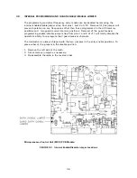
TFM-530 Upload/Download Programming Cable

P/N 993390-1  Wiring Diagram

FIGURE 2-2

TFM-566 Transceiver PC Up/Download Cable - wiring diagram

Note: If your serial port is a 9 pin connector, instead of the 25 pin use a female 9 pin D
connector, connecting:

Yellow -

pin 3

Blue

-

pin 2

Black -

pin 5

Summary of Contents for TFM-566

Page 1: ...DEL TFM 566 P N s 031217 1 3 Installation and Operating Instructions Til Document No 03RE318 Rev B September 2003 Technisonic Industries Limited 240 Traders Boulevard Mississauga Ontario L4Z 1W7 Tel 905 890 2113 Fax 905 890 5338 www til ca ...

Page 2: ...d used in accordance with the instruction manual may cause harmful interference to radio communications Operation of this equipment in a residential area is likely to cause harmful interference in which case the user will be required to correct the interference at his own expense Warning Changes or modifications not expressly approved by Technisonic Industries could void the user s authority to op...

Page 3: ...ivered in the US and Canada as well as a number of single engine fixed wing aircraft The above referenced DO 160C test data is also on file and available from Technisonic to support approval requirements in airframes for which Technisonic does not possess an STC Approved aircraft types are listed in the attachments to the formal STC documents These STC s are the exclusive property of Technisonic a...

Page 4: ...ming Feature 2 7 2 13 Programming CTCSS Tones 2 7 2 14 PC Memory Programming Download Capability 2 9 SECTION 3 INSTALLATION INSTRUCTIONS 3 1 General 3 1 3 2 Equipment Packing Log 3 1 3 3 Transceiver Installation 3 1 3 4 Installation Kit Contents 3 1 3 5 Antenna Installation 3 1 3 6 Installation Pin Locations and Connections 3 1 3 7 Wiring Instructions 3 5 3 7 1 Main Power 28VDC 3 5 3 7 2 Main Grou...

Page 5: ...r s Switches and Controls 2 2 2 2 PC Up Download Cable Wiring Diagram 2 10 3 1 Outline Drawing 3 2 3 2 Wiring Connections 3 4 3 3 Interal Enable Disable Jumper Locations 3 6 3 4 External Adjustment Access Holes 3 8 3 5 VHF Deviation Adjustment Potentiometer Location 3 10 3 6 VLO Deviation Adjustment Potentiometer Location 3 11 ii ...

Page 6: ...h channel and wideband 25 kHz or narrowband 12 5 kHz channel spacing assignment Operating frequency and other related data are presented on a 96 character four line LED matrix display Data entry and function control are performed via a 12 button keypad Preset channels may also be scrolled and scanned through keypad function activation Data may also be entered via a Windows 95 98 NT 2000 ME XP base...

Page 7: ... Max 8 10 Watt Transmit 3 2 A Max 8 10 Watt Dual Trans 5 A Max Frequency Selection 200 memories per band programmed with a Tx Frequency Rx Frequency b Tx Rx CTCSS tone or DPL code c 9 character alpha numeric title Guard Receiver 2 channels programmed with a Tx Frequency Rx Frequency b Tx CTCSS tone or DPL code c 9 character alpha numeric title CTCSS squelch encoder All CTCSS tones available DPL di...

Page 8: ...er than 45 dB Audio Distortion less than 5 Antenna Conducted Emission less than 70 dBm VLO Low Band VHF RECEIVER Sensitivity at 12 dB SINAD Better than 0 5 µV Adjacent Channel Selectivity 70 dB 25 kHz 60 dB 12 5 kHz Spurious Attenuation 80 dB Third Order Intermodulation 70 dB Image Attenuation 60 dB FM Acceptance 6 kHz Hum and Noise Better than 40 dB Audio Distortion less than 5 Antenna Conducted ...

Page 9: ... kHz 12 5kHz mode Spurious Attenuation 70 dB below carrier level Frequency Stability 2 5 ppm Microphone Circuit Carbon or equivalent Sidetone Output 0 5W max into 600S Harmonic Attenuation 60 dB below carrier level FM Hum And Noise 40 dB Audio Input 50 mV at 2 5 kHz into 200 S input circuit for 3 5kHz deviation adjst Audio Distortion Less than 5 ...

Page 10: ...variable dimming mode 13 Selectable 90 second Tx time out feature 14 Quick download of any of the VHF memory positions to the guard memories 15 PC Memory Upload or Download capability 16 Configuration Menu Pressing ENTER RCL and FUNC together while turning the radio on will put it into configuration mode The programming features affected are a DPL Can be turned on or off with th MUP and MDN 4 and ...

Page 11: ...is reached press ENTER and this level will be set for both VHF and VLO bands The factory setting is 23 Important You must set the side tone every time you go through the configuration menu since the position of the knob is taken as the new level regardless of whether or not you made an adjustment FIGURE 2 1 Operator s Switches and Controls ...

Page 12: ...h to the desired guard channel 8 Set the HI LO switch to the desired RF output power 9 Select the desired memory by using the M UP and M DN buttons or the RCL button and a three digit number followed by ENTER 10 To transmit DTMF tones use the keyboard keys while holding the PTT button on the microphone There is a 5 second PTT delay after pressing a key so that you may press several DTMF keys in se...

Page 13: ...e the M UP and M DN keys to scroll through the alphabet numbers and symbols When the desired character is displayed press ENTER to advance to the next character Press 1 to backspace 9 Keep repeating step six until the last space is set The display will show SCAN or LOCKOUT to enable this memory position as part of a scan list or lock it out of the scan list Use the 1 2 3 4 5 and M DN keys to toggl...

Page 14: ...been included in any of the 5 scan lists NOTE Scanning can only be performed on one band either VHF or VLO at a time When the transceiver is in the single mode combined VHF and VLO audio and the scan feature has been invoked on one band it will be interrupted when transmitting on the other band In the Dual mode you are able to transmit on the second band without effecting the scan function on the ...

Page 15: ...urn to the split pair condition you must recall the memory channel again This is quickly done by pressing M UP for one step up then back down one step with the M DN key 2 8 KEYBOARD LOCKOUT FUNCTION The keyboard can be locked out so that accidental pressing of keys does not change frequency etc unknowingly to the operator To lock the keyboard press FUNC then LOCK This will disable all keyboard fun...

Page 16: ...bled when the FUNC 7 mode is turned off in the configuration menu 2 13 PROGRAMMING CTCSS TONES DPL CODES CTCSS tones PL tones or Digital DPL codes can be assigned to each memory channel The guard receiver squelch will operate on noise squelch only but guard 1 and 2 transmit tones or codes can be programmed To program a tone code to a memory channel 1 Select the desired band on the band select swit...

Page 17: ...CTCSS tone should not be enabled 8 Use the keypad to enter the required octal 3 digit DPL Digital Coded Squelch or DCS code A list of all usable and unique octal 3 digit DPL DCS codes follows 017 051 116 156 243 266 346 431 466 612 721 023 053 122 162 244 271 351 432 503 624 731 025 054 125 165 245 274 356 445 506 627 732 026 065 131 172 246 306 364 446 516 631 734 031 071 132 174 251 311 365 452 ...

Page 18: ...tiTDP Program With the program running on your computer a full MultiTDP instruction manual can be loaded by selecting Documentation in PDF format under the Help menu Otherwise to get started pull down the File menu and select TFM 566 The program defaults to serial port com1 but can be set to com2 3 or 4 under the Com Port menu The program is now ready to use You may want to upload data from the ra...

Page 19: ...ble P N 993390 1 Wiring Diagram FIGURE 2 2 TFM 566 Transceiver PC Up Download Cable wiring diagram Note If your serial port is a 9 pin connector instead of the 25 pin use a female 9 pin D connector connecting Yellow pin 3 Blue pin 2 Black pin 5 ...

Page 20: ...NTS The IN 550 installation kit consists of 1 One 15 pin Cannon D mating connector female complete with crimp pins and hood 2 One 9 pin Cannon D mating connector male complete with crimp pins and hood 3 Three BNC antenna mating RF connectors male 3 5 ANTENNA INSTALLATION Antenna Comant P N CI 292 3 or suitable equivalent may be utilized for VHF and the Foxtronics model FLX 6688B antenna and tuning...

Page 21: ...3 2 FIGURE 3 1 Outline Drawing for Model TFM 566 Transceiver ...

Page 22: ... Signal Input 1 7 Main Power 28VDC 8 Main Ground 9 4 ohm Speaker Output 10 4 ohm 600 ohm Output Ground 11 Data Input 12 DF Audio 13 PTT 1 Ground Keying 14 Main Power 28VDC 15 Main Ground 9 Pin D Connections Use MALE Connector Pin Description 1 600 Ohm Output 2 2 PTT 2 Ground Keying 3 Reset 4 Background Debug Signal 5 Ground 6 Programming Voltage In 7 Serial Data Out 8 Serial Data In 9 Mic Signal I...

Page 23: ...3 4 FIGURE 3 2 Wiring connections for the TFM 566 Transceiver ...

Page 24: ...ts 600 ohms and 4 0hms There are two audio outputs available 1 2 600 ohm audio output 1 has audio from both bands and the guard in single operator mode When in dual operator mode 600 ohm output 1 has audio from the VHF band and guard only while the VLO audio will be on the 600 ohm output 2 3 7 6 Audio Output Ground Pin 10 is the ground for both the 4 ohm and 600 ohm audio output signals 3 7 7 Mic ...

Page 25: ...emory positions Removal of the guard receiver programming enable disable jumper strap from pins 1 and 2 of J11 will totally disable the operator s ability to re program the 2 guard receiver channels The transceiver is always shipped with the two jumpers in the entry enable positions To place either of the jumpers in the disable position 1 Remove the left side of the radio 2 Set or remove jumpers a...

Page 26: ...9 5 watts of RF output power 5 Verify that the RF output power is between 9 and 10 watts on 138 000 MHz and 174 000 MHz for VHF or 66 000 MHz and 88 000 MHz for VLO 3 10 TRANSMITTER MICROPHONE LEVEL ADJUSTMENT 1 Set the transceiver operating frequency to 156 000 MHz and connect an appropriate test receiver to the RF output connector Ensure that the output of the transceiver is terminated into a pr...

Page 27: ...3 8 FIGURE 3 4 External Adjustment Access Holes ...

Page 28: ...VHF 1 Remove the bottom cover of the transceiver 2 Set the VHF operating frequency to 157 000 MHz and connect an appropriate test receiver to the RF output connector Ensure that the output of the transceiver is terminated into a proper dummy load 3 Key the transmitter and input a 10 dBm 2 5 VRMS 2 5 kHz audio signal into microphone input 1 4 Adjust the wideband deviation limit potentimeter R30 on ...

Page 29: ... the narrowband deviation limit potentimeter R16 on the VLO Rx Tx module to produce a 2 15 kHz deviation 8 Verify that the deviation does not exceed 5 kHz for wideband and 2 5 kHz for narrowband on 66 000 MHz and 88 000 MHz Re adjust R21 or R16 as required if the deviation exceeds 5 kHz or 2 5 kHz respectively 9 Replace the bottom cover VHF Receiver Transmitter PCB Module Notes R30 is for 25 kHz w...

Page 30: ...3 11 VLO Receiver Transmitter PCB Module Notes R21 is for 25 kHz wideband Deviation Adjustment R16 is for 12 5 kHz narrowband Deviaton Adjustment FIGURE 3 6 Deviation Adjustment Potentiometer Location ...

Page 31: ...ut of view The transponder and encoder should be monitored with ramp test equipment Set the output of the transponder test set to 3db above the output necessary to achieve 90 reply If possible set the ADF to a nearby navigation station Modulate the TFM 566 transmitter on the indicated frequencies for at least 20 seconds Observe the GPS for any degradation in satellite status or availability or fla...

Page 32: ... status or availability or flags FREQUENCIES GPS 1 GPS 2 TFM 566 PASS FAIL PASS FAIL 87 6850 MHz 87 6875 MHz 143 180 MHz 143 1825 MHz 157 5000 MHz 157 5425 MHz NOTES B Determine if the image frequency for the VHF Comm falls within the range of the TFM 566 If so select a set of frequencies that will cause the TFM 566 to be set as close as possible to the image frequency Any one of the many possible...

Page 33: ...IL 132 000 66 0000 135 975 67 9875 135 975 138 0000 121 150 157 5000 131 250 157 5000 128 000 Image FREQUENCIES RESULTS VHF 2 TFM 566 PASS FAIL 132 000 66 0000 135 975 67 9875 135 975 138 0000 121 150 157 5000 131 250 157 5000 128 000 Image NOTES ...

Page 34: ...ollowing chart Modulate the TFM 566 transmitter on the following frequencies for at least 20 seconds Listen for any noise or detected audio signals on the receiver audio look for any moment of flags or needles on the navigation display Note Where indicated by an asterisk required action is to switch ATC 550 on and off as often as necessary FREQUENCIES RESULTS VOR ILS 1 TFM 566 PASS FAIL 108 000 16...

Page 35: ... Glideslope displays Look for any movement of flags or needles on the navigation display FREQUENCIES RESULTS G S 1 TFM 566 PASS FAIL 334 7 108 1 66 9400 334 7 108 1 83 6750 334 7 108 1 167 3500 FREQUENCIES RESULTS G S 1 TFM 566 PASS FAIL 334 7 108 1 66 9400 334 7 108 1 83 6750 334 7 108 1 167 3500 NOTES ...

Page 36: ... following frequency for at least 20 seconds Observe the Transponder for any spurious replys or loss of reply to test set FREQUENCIES TRANSPONDER 1 TRANSPONDER 2 TFM 566 PASS FAIL PASS FAIL 85 0000 MHz 85 8350 MHz 171 6650 MHz 171 6700 MHz NOTES ...

Page 37: ...ve the DME displays Look for loss of distance information on the display FREQUENCIES RESULTS DME 1 TFM 566 PASS FAIL 978 108 0 81 5000 978 108 0 163 1020 112 1 85 0000 1020 112 1 170 FREQUENCIES RESULTS DME 2 TFM 566 PASS FAIL 978 108 0 81 5000 978 108 0 163 1020 112 1 85 0000 1020 112 1 170 NOTES ...

Page 38: ...turning the ATC 550 on and off as often as required listen for any noise or detected audio signals on the HF receiver audio FREQUENCIES RESULTS HF 1 PASS FAIL 16 MHz FREQUENCIES RESULTS HF 2 PASS FAIL 16 MHz NOTES ...

Page 39: ...bility augmentation system Modulate the TFM 566 transmitter on the above frequencies for at least 20 seconds Observe any effect on the autopilot or stability augmentation system Observations I Perform a coupled ILS approach to the aircraft s certified limits Modulate the TFM 566 transmitter on the above frequencies for at least 20 seconds Observe any effect on the autopilot Repeat for second fligh...

Page 40: ...y anomalies that occur while transmitting or switching the ATC 550 on and off Assess the results STEP SYSTEM PASS FAIL NOTES 1 Com 1 2 VLO 66 88 MHz Band 2 Transponder Encoder VHF 138 174 MHz Band 3 ADF 1 2 4 VG 5 Glideslope 1 2 VLO 66 88 MHz Band 6 VOR LOC 1 2 VLO 66 88 MHz Band 7 Directional Gyro ...

Page 41: ...STEP SYSTEM PASS FAIL NOTES A 11 8 Compass 9 Fuel Pressure 10 Oil Temp 11 Amps 12 Bus Voltage 13 Fuel 14 Nt 15 TOT ...

Page 42: ...STEP SYSTEM PASS FAIL NOTES A 12 16 Torque 17 Annunciators 18 Digital Clock 19 Oil Pressure ...

Page 43: ...STEP SYSTEM PASS FAIL NOTES A 13 NOTES ...

Reviews: