background image


15


TS8200D Series


Micro-Meter Mix User Guide
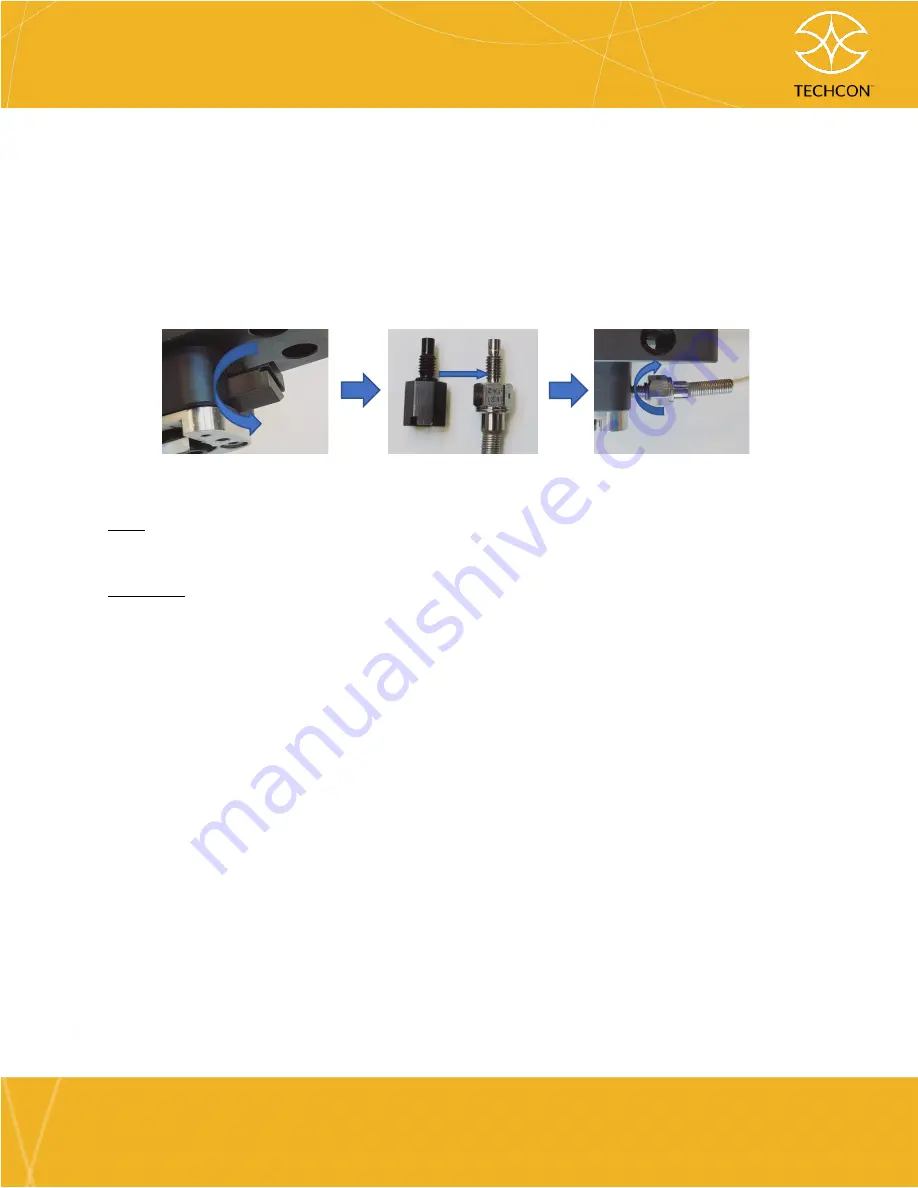
 

techcon.com/contact-us      


a.


Remove both fluid manifold plug screws and O-rings.  

b.


Mount sensors. Note: If the sensors are missing O-rings, use the O-rings 
from the plugs.   

c.


Screw the sensors by hand and use 8.0 mm wrench, crescent wrench, or 
flat head screwdriver for the final tightening.  


Tip: 

To avoid cable “curling

,

 do not install sensors to the controller before fastening 

the sensors to the pump.


Warning!

 The surface of the sensors is extremely sensitive. Therefore, take extra 

caution when handling these sensors and avoid hitting them against other surfaces. 


10.


Install Calibration Adaptor  
 
The calibration adaptor is required whenever calibration is performed, when a 
new fluid is introduced, when the valve is disassembled & reassembled, or when 
the stators or rotors are changed. Connecting calibration adaptor can protect 
the TS8200D from having direct contact with the material as it exits the pump.  
 

a.


Mount  the  1:1/2:1  K-type  Nozzle  Locking  Plate  and  use  a  2.0mm  hex 
wrench to fasten screws into place. 


b.


Mount    the  calibration  adaptor  and  use  a  2.5mm  hex  wrench  to  fasten 
screws into place.  


c.


Make  sure  that  the  calibration  adaptor  rest  evenly  against  the  nozzle 
locking plate.  

Summary of Contents for TS8200D Series

Page 1: ... contact us ______________________________________________________________________ ______________________________________________________________________ TS8200D Series Micro Meter Mix True volumetric measuring mixing and dispensing of 2 component materials ...

Page 2: ...e covered in this guide Nevertheless if you need further assistance please do not hesitate to contact our Techcon support team Detailed contact information is provided on the last page of this document From Our Team Thank you for choosing and putting your trust in our fluid dispensing systems to solve your dispensing needs Over the years we have strived to be the brand of choice for customers look...

Page 3: ...ng Inspection 10 4 Installation 12 4 1 Out of the Box Assembly Instructions 12 4 2 Mounting the Pumps 16 4 3 Dispense Fluid Set Up 16 4 4 Final System Layout 18 4 5 Venting and Purging the Pumps 18 4 6 Calibrating the Pumps 22 4 7 Determining Controller Settings and Final Set Up 22 5 Maintenance and Cleaning 26 5 1 Preparations Before Disassembly 27 5 2 Pump Disassembly 28 5 3 Pump Cleaning 31 5 4...

Page 4: ...ccurate mixing and dispensing output Every component of the pump was designed to the highest tolerances and manufactured to the strictest degree of precision ensuring world class accuracy and repeatability 1 1 Key Features and Benefits True Volumetric Positive Displacement technology to achieve 1 variation in dispense output High quality mixing to ensure proper material curing Continuous Flow with...

Page 5: ...ump is available in three different sizes The size is determined by the stator and rotor selection 100 Series Stator Rotor o 0 012 ml rev per pump o Minimum dispense volume 0 012ml per pump o Flow rate 0 12 1 21 ml min 200 Series Stator Rotor o 0 055 ml rev per pump o Minimum dispense volume 0 055ml per pump o Flow rate 0 65 6 90 ml min 300 Series Stator Rotor o 0 080 ml rev per pump o Minimum dis...

Page 6: ...Micro Meter Mix pump dispenses fluid with a positive displacement action using progressive cavity technology Fluid is introduced into the pump through the fluid inlet and begins to occupy the empty space that makes up the upper valve body The stator and rotor form a perfect seal preventing any material from flowing beyond there mating point As the rotor rotates the fluid is allowed to flow from on...

Page 7: ...The TS580D MM allows users to make the most use out of there dispensing pump Controller features include dispensing in volume weight or timed mode quick and simple programing to dispense lines access to over 50 different memory locations for quick profile change and remote access control of programs via ethernet 24 VDC encoder motor Fluid Inlet Rotor Stator Outlet Fluid Manifold Process Fluid ...

Page 8: ...8 ml for 300 012 ml for 100 08 ml for 300 Repeatability 1 per pump Dispense Accuracy 99 Fluid inlet pressure Maximum Up to 2 bar 30 psi for viscosity of 1 000 cps or less up to 5 5 bar 80 psi for viscosity greater than 1 000 cps Fluid inlet type 1 8 NPT Mixing Nozzle K type Standard Bayonet Mounting M4 x 35MM SHC S S Wetted Parts Stator Housing Anodized Aluminum Rotor Carbide Stator PFE Flex Coupl...

Page 9: ...osity of 1000 Cps or lower The pump can handle up to 5 5 bar for 300K Cps viscosity fluid Accuracy measurements are taken for one complete revolution Absolute deviation in volumetric dispense accuracy exist for incomplete revolutions and may also occur for certain dispensing fluid 2 1 Pump Dimensions Units mm ...

Page 10: ...10 TS8200D Series Micro Meter Mix User Guide techcon com contact us 3 Unpacking Inspection ...

Page 11: ... LUER LOCK BLACK NYLON 2 14 TSD931 96 FEMALE LUER WITH 1 8 NPT THREAD 2 15 TSD931 82B MALE ADAPTER WITH LUER LOCK BLACK NYLON 2 16 7000 7320 USER GUIDE METER MIX 1 17 7000 7310 QUICK SETUP INSTRUCTIONS SHEET METER MIX 1 18 7000 4340 LABEL PACKAGING VALVE 1 19 4100 0059 LABEL LEAD FREE RoHS COMPLIANT 500 ROLL 1 20 7000 3640 AW ARTWORK STANDARD PACKAGE LARGE LABEL 1 21 1400 0280 FOAM INSERT METER MI...

Page 12: ... rotor and stator Excessive friction between dry components may damage stators and effect pumps performance Do not use water Using water may damage the pump Recommend using conditioning fluid for cleaning 1 Apply the dispensing fluid or any appropriate lubricant compatible with the dispensing fluid to the surface of the rotor 2 Wet the stator opening by squeezing a small amount of the dispensing f...

Page 13: ... assembled pump and pump housing The engraved labels RESIN and HARDENER should be facing you Insert and fasten four 4 3 0 mm hex screws with lock washers in the order shown in the image below Make sure the two now assembled pumps are vertically symmetrical and not flaring outwards Make sure there are no gaps or any visible light between pump housing and mating parts If there are issues relieve ten...

Page 14: ...ce the Accessories section for information on fluid inlet fittings It is recommended that Teflon tape be applied to the thread of the fluid inlet fitting prior to installation 9 Mount pressure sensors optional feature TS8200D is available with sensors for monitoring dosing pressure With this feature you are able to keep closer track of any output pressure changes caused by factors other than visco...

Page 15: ...ke extra caution when handling these sensors and avoid hitting them against other surfaces 10 Install Calibration Adaptor The calibration adaptor is required whenever calibration is performed when a new fluid is introduced when the valve is disassembled reassembled or when the stators or rotors are changed Connecting calibration adaptor can protect the TS8200D from having direct contact with the m...

Page 16: ...280 mounting plate The valve may be mounted using holes marked with a red circle 4 3 Dispense Fluid Set Up Warning For your safety Follow the safety guidelines outlined by the manufacturer for instructions on handling the process fluid Do not overtighten fittings Doing so may damage pump housing components Do not use water for priming or cleaning the pump Doing so may damage the pump Do not run th...

Page 17: ...ews are present and well fastened on both the front and back of the pumps Tip Avoid over tightening vent screws Over tightening may lead to tears to the vent seal O ring 3 Connect the fluid supply to the fluid inlet of the pump If using a fluid reservoir reference the Accessories Section for information on compatible fluid lines Make sure the resin is connected to the pump with the RESIN label and...

Page 18: ...ule is to begin pressurizing the fluid starting from 0 psi Reason Higher pressures may cause low viscosity fluids to spray from the output when purging or from the pump housing if the pump is incorrectly assembled b Set the fluid pressure to around 0 3 bar 5 psi The fluid pressure will depend on the viscosity of the material For this sample setup we are assuming low viscosity less than 1000 cps mP...

Page 19: ...ust the tension on the screws and inspect the O ring seals Reference disassembly section of user guide for additional information d Purging and Venting RESIN Pump 1 i Place a clean towel or a container under the pump Tip Never use the same cleaning towel for both process fluids Mixing the fluids may lead to undesired chemical reactions ii To purge the resin though the manifold 1 Navigate to the Ho...

Page 20: ...nt screw by turning in the counterclockwise direction Loosen screw in 1 revolution increments At around the 6th 7th revolution you should begin to see material seep out Allow material to escape until no more air bubbles are observed Warning Do not loosen to more than 8 complete revolutions Doing so will unfasten the screw allowing pressurized material to spray out 3 Fasten the venting screw Avoid ...

Page 21: ...elect the Purge Pump 2 icon Note Purge Pump 2 icon will dispense the hardener at a safe speed for initial priming of the pump 4 Press the foot switch 5 Allow the fluid to flow from the manifold until a steady stream of air free material is observed 6 Release the foot switch 7 We are now done purging pump 2 iii To vent the hardener 1 Have a cleaning towel or container under the pump ready to catch ...

Page 22: ...g the TS8200D Micro Meter Mix we will need to calibrate each pump Go to the TS580D Controller User Guide for calibration instructions Return here once calibration has been completed Tips During the calibration process it is recommended that you collect and weigh a sample size of at least 5 samples for the MEDIUM weight entry to confirm the pumps are dispensing consistently If air bubbles are still...

Page 23: ...ls 2 0 mm hex wrench If using 1 1 2 1 bayonet socket type The static mixing nozzle can be mounted directly onto the pump using the already installed 1 1 2 1 K type nozzle locking plate Align the holes and rotating cap of the mixing nozzle with the holes of the fluid manifold and keyed entry of the base plate adaptor Insert the nozzle and make sure it rests evenly with the base of the fluid manifol...

Page 24: ... base plate adapter followed by the bayonet socket base plate adapter Align the holes and rotating cap of the mixing nozzle with the holes of the fluid manifold and keyed entry of the base plate adaptor Insert the nozzle and make sure it rests evenly with the base of the fluid manifold Lock into place by rotating the mixing nozzle s rotating cap counterclockwise Pull on the nozzle to confirm it is...

Page 25: ...onfirm bayonet base plate contains x2 O rings 3 Install bayonet base plate adaptor 4 Twist and lock 5 Pull on the nozzle to confirm it is securely locked into place The pump is now ready for use Tips 1 Viscosity can affect the rate of dispense even at a set motor speed Dual component media usually have different viscosity for part A and part B If ...

Page 26: ... pump type 4 Keep in mind the pot life of the material Leaving mixed material during breaks or overnight may render the mixing nozzle unusable upon start up One possible solution to extend the life of mixing nozzles is to rinse fill completely the mixing nozzle with one of the two materials Doing so may prevent the two components from reacting and curing Please note this solution is not suitable f...

Page 27: ... 3 mm hex wrench for removing rotor set screw Phillips 2 screwdriver 5 1 Preparations Before Disassembly 1 Flush purge all material from the pump with cleaning fluid The recommended purging fluid is Techcon 7305XCON dispensing conditioner The conditioner removes the majority of the material residue from the material path and conditions the pump for future use Procedure Release material feed pressu...

Page 28: ...emove the mixing nozzle adaptor 2 Use an 8 mm 5 16 wrench or crescent wrench to remove pressure sensors or use a flat head screwdriver to remove manifold plugs Replace plug screw O rings if damaged Tips The surface of the sensors is extremely sensitive Therefore take extra caution when handling these sensors and avoid hitting them against other surfaces Label sensors such that the same sensor is m...

Page 29: ... Removing the stators 1 Connect the pump to the controller Using Purge mode press the footswitch to run the pump The stator should begin to unwind 2 Once the stator has cleared the four 4 locking notches manually rotate the stator in the counterclockwise direction to remove the stator 9 If not done so already use a 2 0 mm hex wrench to remove four 4 stator housing hex screws and pull out stator ho...

Page 30: ...00 or 300 series Tip When re installing the set screw it is recommended that a low strength thread locking fluid be used to hold the set screw in place such as Loctite 222 12 Use a 1 5 mm hex wrench to remove flex coupling 13 Remove the shaft seal block and inspect shaft seal Replace shaft seal if warn 14 Inspect pump O ring seal and cup seal on the bearing block assembly for wear and tear Replace...

Page 31: ...ws holding together the motor mounting plate and the bearing block assembly 16 Inspect and confirm the area that houses the motor coupling is clean and free of any process fluids 17 Inspect coupling disc Replace if worn 5 3 Pump Cleaning Refer to product specifications for compatible solvents to use to clean wetted parts ...

Page 32: ...Process 1 Use cleaning towels to remove excess material from the surface of all wetted parts Tip Never use the same cleaning towel for both process fluids Mixing the fluids may lead to undesired chemical reactions 2 Use tweezers to remove O rings and to remove dried hardened material from the side walls of the fluid housings 3 Use scrapping spatula to remove any cured or dried material stuck to th...

Page 33: ... residue from stator housing side walls 5 Use cotton swabs to remove material stuck to the base of the shaft seal block fluid manifold and stator housing 6 Use the small brush to clean fluid path channels of the manifold fluid inlet openings vent screw openings calibration adaptor and other nozzle adaptor openings ...

Page 34: ...r Things to keep in mind during assembly 1 Check all fastening screws and connections to ensure they are securely tightened re tighten if needed 2 Check and replace all parts that show signs of wear and tear This includes seals stators rotor or fluid inlet fittings 3 If you replace the rotor or remove the flex coupling make sure to apply low strength threadlocker to the set screws 4 Make sure to a...

Page 35: ...ries Micro Meter Mix User Guide techcon com contact us 5 Reference the installation procedure for instructions on how to initialize your pumps 6 Inspect the valve for leaking when the process fluid is re introduced ...

Page 36: ...Coupling Disc 7509 0530 Rotor 5 0 mm Pitch 200 Series 14 7509 0950 Coupling Half Top 7509 0820 Rotor 6 5 mm Pitch 300 Series 15 2800 0903 Set Screw M3 x 0 5mm x 6MM LG S S 2 7509 9430 Flex Coupling 16 2800 0901 Screw M3 x 6mm LG FH PHIL MACH S S 3 2800 0836 Set Screw M2 5 x 3mm LG Socket Cup S S 17 7509 0980 Motor Mounting Plate 4 2800 1019 Screw M2 5 x 25mm LG SHC S S 18 2800 0897 Screw M2 5 x 14...

Page 37: ...Forming S S 8 7509 0970 Shaft Seal Block 22 7509 9400 Assy Motor Connector 9 7509 0990 Shaft Seal 23 7509 1450 Stator Housing 10 3300 0353 Cup Seal UHMW Jacket S S Spring 24 3300 0696 Vent Seal Washer 8 15 ID x 31 OD x 52 THK Fluorosilicone 11 3300 0690 O Ring Square ID x 7 8 OD X 1 16 W BUNA N 25 2800 0431 Vent Screw M4 x 8mm LG PAN PHIL MARC S S 12 7509 9340 Bearing Block Assembly FA 26 3300 059...

Page 38: ...ct us Pump Housing and Manifold Assembly Part Number Description 7509 1460 Pump Housing 7509 1150 Fluid Manifold K type Nozzle 1 1 3300 0656 GASKET 1 2 ID X 5 8 X 1 16 W VITON 7509 1190 3300 0662 Fluid Manifold Plug Screws Plug Screw O rings 3mm ID x 1 mm CS EPDM ...

Page 39: ...ors Part Number Description 8200D 000 001 Calibration Adaptor Assembly Includes x1 7509 1210 Calibration Adaptor x2 3300 0662 O rings 3mm x 1mm CS EPDM x2 2800 1030 Captive Screws 7509 1160 1 1 2 1 K Type Nozzle Locking Plate 8200D 000 006 4 1 10 1 K Type Nozzle Adaptor Includes x1 7509 1170 K Type Nozzle Adaptor x2 3300 0662 O rings 3mm x 1mm CS EPDM x2 2800 1033 Screws M3 x 6mm SHC S S ...

Page 40: ...2 O rings 3mm x 1mm CS EPDM Syringe Bracket Part Number Description TS8200D SYBRACKET Syringe Bracket for Syringe Barrels Includes x2 Syringe Holder 30 55cc x2 Syringe Holder adaptors 10cc x2 Syringe Holder adaptor 6cc x2 Syringe Holder adaptor 3cc Mounting Part Number Description 2800 1031 Mounting Screws M4 x 35MM SHC S S 7506 0280 Mounting Bracket for TSR robot ...

Page 41: ...NKIT Cleaning Kit Includes x1 TSD2106 1 Cleaning Brush Small 0 15 3 8mm x1 Cleaning Brush Large 0 45 11 4mm x1 Wrench Hex L key 1 5mm x 1 3 4 x1 Wrench Hex L key 2 0mm x 1 57 64 x1 Wrench Hex L key 1 3mm x 2 13 16 x1 Wrench Hex L key 3 0mm x4 7509 0990 Shaft seals x2 3300 0353 Cup Seals x4 3300 0696 Vent Seal Washers ...

Page 42: ...iption 8200D PS Pressure Sensor Part Number Description 8200D SEALKIT Seal Kit Includes x2 Gasket 1 2 ID X 5 8 X 1 16 W VITON 2x Cup Seal UHMW S S Spring TS7000 x4 Shaft Seal x4 O Ring Square 3 4 ID X 7 8 OD X 1 16 W BUNA N 4x Washer 8 15 ID X 31 OD X 52 THK Fluorosilicone 7305XCON Cleaning Conditioner 30cc ...

Page 43: ...re Inconsistent Shot size Fluid dried or cured Replace with new fresh fluid Fluid pressure fluctuating Make sure fluid pressure is constant Valve on time is too short Increase valve on time Excessive motor reverse time Reduce reverse time or turn off completely Inconsistent Shot size Air trapped in fluid Purge valve properly Skipped dots Fluid drools after the valve turned off Intermittent motor s...

Page 44: ... 80 1 54 12 6 2 1 0 42 2 10 1 89 9 45 2 31 11 5 0 95 4 20 1 16 4 20 1 90 11 5 4 1 0 70 1 75 3 15 7 87 3 85 9 62 0 79 7 00 0 97 7 00 3 15 9 63 6 1 0 98 1 63 4 41 7 35 5 39 9 00 1 00 7 35 1 00 9 00 4 41 9 00 8 1 1 26 1 57 5 67 7 01 6 93 8 66 1 26 7 10 1 26 8 67 5 67 8 66 10 1 1 54 1 54 6 93 6 93 8 47 8 47 1 54 6 93 1 54 8 50 6 93 8 50 Units ml min Flows are based on average calibration on a standard...

Page 45: ...f the company In no event shall the Manufacturer be liable for consequential or incidental damages A return authorization is required from Techcon Systems prior to shipping a defective unit to the factory Manufacturer reserves the right to make engineering product modifications without notice All returns must be issued with a Returns Authorization number prior to return Send warranty returns to Am...

Reviews: