


21
13 MAINTENANCE
The TS6500 Mixer is designed and built to be relatively maintenance
free. To assure trouble free operation, the following
recommendations should be followed:
1. Make certain the air supply is clean and dry.
2. Avoid connecting the unit to excessive moisture or solvent
saturation.
3. Use only Amyl Alcohol to clean outside surface of the main
housing.
4. Use only soft cloth to clean the LCD.
5. Clean the injection rod regularly with cleaning solvent
6. Clean the tray regularly with cleaning solvent
14 LIMITED WARRANTY
OK International warrants this product to the original purchaser for a
period of one (1) year from date of purchase to be free from material
and workmanship defects but not normal wear-and-tear, abuse and
faulty installation.
Defective product or subassembly and
components under warranty will be repaired or replaced (at OK
International's
option) free of charge. Customer with defective
product under warranty must contact the nearest OK International
office or distributor to secure a return authorization prior to shipping
the product to the assigned OK International authorized service
center. For nearest OK International office or distributor contact
information, please visit www.okinternational.com. OK International
reserves the right to make engineering product changes without
notice.
22
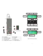
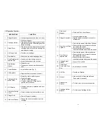
15 APPENDIX
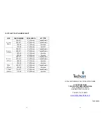
15.1 Spare Parts List
ITEM PART
NUMBER
DESCRIPTION
QTY
1
7091-9010
CARTRIDGE HOLDER ASSEMBLY, 2.5oz/6oz/8oz
1
7091-9030
CARTRIDGE HOLDER ASSEMBLY, 20 oz
1
2
7091-9040
PLUNGER ASSEMBLY, 2.5oz/6oz/8oz
1
7091-9060
PLUNGER ASSEMBLY, 20 oz
1
3
7091-0420
HOLDER, PLUNGER ASSEMBLY
1
4 7091-0120
SPINDLE
EXTENSION
1
5
7091-0530
WRENCH, THIN HEAD, 19mm
1
6
7091-9080
AIR FILER ASSEMBLY
(Filter only = TSD800-6)
1
7 6002-0703
POWER
CORD
1
8 7091-0430
TRAY
1
9
5100-0079
START PUSH BUTTON
1
10 TSD500-29
AIR
REGULATOR
1
11 5100-0078
E-STOP
SWITCH
1
12 7091-0510
LCD
COVER
1
13 7091-9070
SPINDLE
ASSEMBLY
1
14 7091-0430
SAFTY
DOOR
1
15 5100-0077
INTERLOCK
SWITCH
1
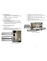
Figure 18.0 Main Assemly


