
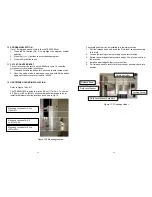


9
5.2 Operation Function
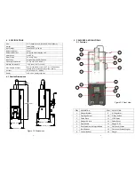
DESCRIPTION FUNCTION
1 Plunger
Bracket
•
Holds plunger assembly when not in use
2 Cartridge
Holder
•
Holds cartridge kit
•
Operates with the plunger assembly and
guide block to drive the cartridge up and
down for mixing
3 Guide
Block
•
Operates with the plunger assembly and
cartridge holder to drive the cartridge up
and down for mixing
4
Air Plunger Inlet
•
Provides air to plunger
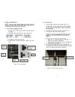
5 Door
Handle
•
Secures cover and disengages door
6
Drive Spindle with
Injection Rod
•
Rotates mix rods during mix cycle
•
Injects the hardener into the resin
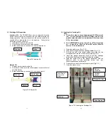
7
Start Buttons
(Green)
•
Starts the unit
•
Press green buttons simultaneously to
start
8 Control
Buttons
•
Input buttons (see Fig. 5)
9 Air
Regulator
•
Regulate the air pressure to the unit
10
Emergency Stop
button (Red)
•
Stops the Unit in an Emergency
•
Press to Engage
•
“E-Stop!” will be displayed,
•
To reset, rotate the E-Stop knob a
quarter turn clockwise
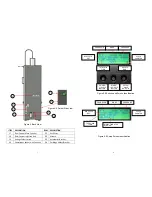
11 LCD
Display
•
Displays unit status, operation and error
messages.
12
Protective (Safety)
Cover
•
Protect operators when machine in use
13 Plunger
Disk
•
Part or Plunger Assembly
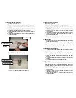
14 Fluid Level Sensor
•
Senses the fluid level at the top of the
cartridge
10
15
Fluid Level
Magnet
•
Work with Fluid Level Sensor
16 Plunger
Assembly
•
Locks cartridge in place
•
Applies steady pressure to prevent air
entrapment
17
Flow Control; Main
Cylinder
•
Controls the speed of the Main Cylinder
•
Rotate the flow control screw clockwise
to increase the speed.
•
Rotate the flow control screw
counterclockwise to decrease the speed
18
Flow Control;
Injection Rod
•
Controls the speed of the injection rod
•
Rotate the flow control screw clockwise
to increase the speed.
•
Rotate the flow control screw
counterclockwise to decrease the speed
19
Voltage Select
Switch
•
Select 115V or 230V
20
Power Input
Socket with Fuse
Box
•
Input power connection
21 Air
Filter
•
Provide air filtration
22 Wrench
•
Use to install Air filter assembly and
Drive spindle assembly
23
Accessories
Bracket
•
To hold wrench or other accessories
24
Cartridge Holder
Bracket
•
To hold extra Cartridge Holder


