background image


5

4 SPECIFICATIONS 


Size  

15.7” (398mm) X 21.2”(538mm) X 40.6”(1032mm) 

Weight  

80lbs (36kg) 

Input Voltage  

120/230 VAC, 50/60 Hz 

Rated Input Power 

200W 

Rated Input Current 

2A @ 120 VAC / 1A@230 VAC 

Motor Speed 

139 RPM 

Motor Torque 

42 in-lb (4.7 Nm)  

Indoor  Use 

Altitude up to 6,562ft  (2,000m)  

Operating Temperature 

32˚F to 122˚F (0˚C to 50˚C) 

Storage Temperature 

-10˚C to 60˚C (14˚F to 140˚F) 

Max. Relative Humidity 

80% for temperature up to 87.8˚F ( 31˚C) Decreasing 
linearly to 50% relative humility at 104˚F (40˚C) 

Air Input 

50 to 100psi (3.5 – 6.9 Bar) 

Display 

LCD 20 X 4 display segments 


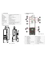
4.1  Outside Dimensions 


398mm [15.7"]

319mm [12.6"]

380mm [15.0"]

537mm [21.2"]

120mm [4.7"]

1032mm [40.6"]

Figure 1.0 Dimensions 


6

5 FEATURES 

AND 

FUNCTIONS 

5.1 Features 


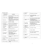
ITEM


DESCRIPTION


ITEM


DESCRIPTION


1


Plunger


Bracket


9


Air


Regulator


2


Cartridge


Holder


10


E

Stop


Button


3


Guide


Block


11


LCD


Display


4


Plunger


Air


Inlet


12


Safety


Cover


5


Door


Handle


13


Plunger


Disk


6


Drive


Spindle


with


Injection


Rod


14


Fluid


Level


Sensor


7


Start


Buttons


15


Fluid


Level


Sensor


Magnet


8


Control


Buttons


16


Plunger


Figure 2.0 Front View 

 1

 2

15 

16 

 3

 4

 5

13 

 6

12 

11 

 7

 7

  8

 9

10 

14 

Summary of Contents for TS6500

Page 1: ...on the Unit 12 6 3 Cartridge Kit Preparation 13 6 4 Loading the Cartridge Kit 14 6 5 Spindle Extension Installation 15 6 6 Mix Cycle Program Setup 16 6 7 Start the Unit 16 6 8 Unloading the Cartridge...

Page 2: ...roper handling and safety precautions Do not smoke or use open flame when flammable materials are being dispensed This equipment is for indoor use only 4 2 DESCRIPTION The TS6500CIM Series Automatic T...

Page 3: ...0 relative humility at 104 F 40 C Air Input 50 to 100psi 3 5 6 9 Bar Display LCD 20 X 4 display segments 4 1 Outside Dimensions 398mm 15 7 319mm 12 6 380mm 15 0 537mm 21 2 120mm 4 7 1032mm 40 6 Figure...

Page 4: ...4 Cartridge Holder Bracket Figure 4 0 Partial Side View Figure 3 Back View 24 23 22 21 17 18 19 20 8 Figure 5 0 Buttons and Screen Identification MIX CYCLE SET PROGRAM MODE PRESSURE TOTAL MIX TIME SAF...

Page 5: ...lays unit status operation and error messages 12 Protective Safety Cover Protect operators when machine in use 13 Plunger Disk Part or Plunger Assembly 14 Fluid Level Sensor Senses the fluid level at...

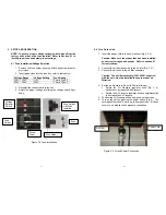
Page 6: ...rn On the Unit 1 Insert the power cord to the power socket Fig 3 20 Caution Make sure the proper fuse has been installed and correct voltage has been set Refer to section 6 1 for instructions 2 Connec...

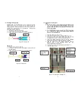
Page 7: ...etup to mix cartridge kit with 8 203mm mix rod To mix cartridge kit with 6 152mm mix rod the spindle extension needs to be installed Refer to section 6 5 for instructions b The TS6500CIM 6 is setup to...

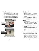
Page 8: ...and button to adjust delay time 6 Press and hold the Setup button for 3 seconds to save data The unit is now ready to run 6 7 Start the unit 1 Ensure the unit is in the Automatic Mode and the desired...

Page 9: ...not fully closed Check power cord connections Turn Emergency button clockwise to release Closed safety door LCD does not light No power input Check power cord connections Check Fuse Turn on power Air...

Page 10: ...6 0 oz 177ml kit To mix the 2 5 74ml or 8 0 oz 237ml kit the cartridge holder needs to be re install at different mounting locations as shown in Fig 10 Mounting Location for 2 5 oz 74ml Kit Mounting...

Page 11: ...h defective product under warranty must contact the nearest OK International office or distributor to secure a return authorization prior to shipping the product to the assigned OK International autho...

Page 12: ...0 0060 VOLTAGE SELECT SWITCH 1 44 2100 0372 POWER CONNECTOR 1 Figure 19 0 Inside Front Cover Assembly 24 Figure 19 0 Inside Assembly Level 2 ITEM PART NUMBER DESCRIPTION QTY 45 TSD650 21 SOLENOID VALV...

Page 13: ...m Injection 600 80 8 203mm Injection 8 0 oz 237ml 800 61T 6 152mm Taped Barrier 800 81T 8 203mm Taped Barrier 800 60 6 152mm Injection 800 80 8 203mm Injection 20 oz 591ml 200 81T 8 203mm Taped Barrie...

Reviews: