


2-5
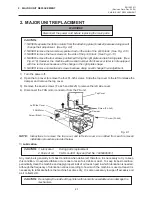
2. MAJOR UNIT REPLACEMENT
EM18-33011
(Revision Date: Apr. 05 '94)
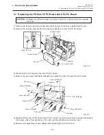
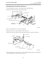
2.3 Replacing the Ribbon Motors
2.3 Replacing the Ribbon Motors
CAUTION: NEVER separate the ribbon motors from the attaching plate because doing so will
change their adjustment.
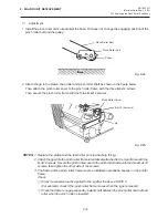
1) Disconnect the connector and remove the two SM-3x5B screws to detach the ribbon motors.
Fig. 2-8
2) Replace the ribbon motors, then align the dowels to attach the ribbon motors. Reassemble in the
reverse order of removal.
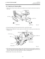
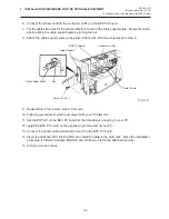
2.4 Replacing the Take-up Motor
CAUTION: NEVER separate the take-up motor from the bracket because doing so will change
the adjustment.
NOTE:
The following procedure can be employed without removing the top cover and left side cover.
1) Remove the four FL-3x5 screws to detach the motor cover.
2) Remove the connector for the rewind full sensor (LED).
3) Disconnect the connector from the CN1 on the PWM PC board and remove the two FL-3x5 screws
to detach the take-up motor.
Fig. 2-9
4) Replace the take-up motor, then align the dowels to attach the motor cover and rewind full sensor
(Tr).
Dowels
Attaching Plate
FLOIL G-488
FLOIL G-488
Attaching Plate
Ribbon Motor
Screw (SM-3x5B)
Connector (Red)
Connector (Black)
Screw (SM-3x5B)
Connector (CN1)
Screw (FL-3x5)
Screw (FL-3x5)
PWM PC Board
Bracket
Take-up Motor
Connector
Ribbon Motor
Motor Cover


