58
9. Communication
This chapter contains:
l
Communication ports (RS-232 and USB)
l
Network Management Card (Optional)
l
UPS Management Software
l
REPO
9.1 RS-232 and USB Communication Ports
To establish communication between the UPS and a computer, connect
your computer to one of the UPS communication ports using an
appropriate communication cable.
When the communication cable is installed, power management
software can exchange data between your computer and the UPS. The
software will obtain the detailed information of the UPS on the status of
the power environment. If power emergency occurs, the software
initiates the saving of all data and an orderly shutdown of the equipment.
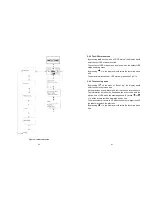
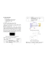
The cable pins for the RS-232 communication port are identified in figure
9-1, and the pin functions are described in Table 3.
Figure.9-1 RS-232 Communication Port (DB-9 Connector)
Table 3 RS-232 Communication Port Pin Assignment
Pin
Number
Signal
Name
Function
Direction from
the UPS
1
Battery Low signal
Out
2
RxD
Transmit to ext. PC/Server
RS232
3
TxD
Receive from ext. PC/Server
RS232
5
GND
Signal common
--
59
7
Not used
--
8
On Battery signal/Main failure
Out
9
Vdc Power
(
+12V
)
This pin is connected via a
jumper to pin 2 of SNMP
connector
Out
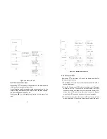
Figure.9-2 RS-232 Communication Port
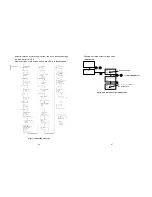
Figure. 9-3 Pin1/Pin8 typical application
Notes:
The Pin 1 & 8 are driven by Transistor ( aren’t a relay), so
maximum voltage of ‘+V’ is 30Vdc, the maximum current is 45mA.
Summary of Contents for AP160N-10K
Page 33: ...62 614 08108 00...

