background image

Front Shock Location

; Leaning the shocks in (mounting them closer to the center of the tower) will give a smoother transition as you

enter into turns and improve consistency but will yield less total steering and give a slower reaction. This might be helpful on high bite
surfaces. Standing the shocks up (mounting them further out from the center of the tower) will increase responsiveness and generate
more total steering. Forward traction is also increased, as is on-power steering. When moving the shocks to a more upright position
you may find that you will have to change to a softer spring to smooth out the reaction. This might work well on shorter more
technical  tracks.

Front Toe-in/Out

;


is the parallel relationship of front tires to one another. Toe-in/out adjustments are made by changing the total

length of the steering rods. If the front tires appear to be pointing inward to a spot in front of the car (toe-in) you can expect the car
to react a little slower but have a little more steering from the middle of the turn out. The opposite is true if the front tires appear to be
pointing to points in front and to either side of the car (toe-out). This (toe-out) will make the car turn into the corner better but will
allow less steering from the middle of the corner out.

Front Camber Link

; Making the camber link shorter (moving it further away from the center of the tower) tends to give more off-

power steering into the turn but can also make the steering feel a bit erratic. Making the camber link longer (moving it closer to the
center of the tower) will slow down the reaction of the steering but will make the chassis more forgiving.

Camber

;


refers to the angle of the wheels/tires in relation to the track surface when viewed from the front or back. Negative camber

means that the top of the tire leans inward toward the chassis. Positive camber means the top of the tire leans out away from the
chassis. You should never need to run positive camber and will always want to run at least a little negative camber. You can use any
square object to check this by placing it so one edge is flat on the surface and the other is up against the outer surface of the wheel.
There should always be at least a slight gap at the top of the wheel (negative camber). There should never be a gap at the bottom of
the wheel (positive camber). Adding 1 degree front camber will typically increase steering but ideally the camber is adjusted to get even
tire wear across the tire.

Front Kickup/Anti-dive

;


is the angle of the front arms in relation to the track surface. The kickup is controlled by the pivot blocks

that mount the inner hinge pins of the front suspension arms to the chassis. You have three options with the included mounts, 0, 2, and
4 degrees. The front is marked with a "4F" and a "0F" at the middle of the surface facing forward. If this block is mounted with the
"4F" at the top there is 4 degrees of kickup, if the "0F" is at the top there is no kickup. The other included pivot block is labeled "2F"
and gives 2 degrees. The "4F" setting is best for bumpy surfaces and makes the car very forgiving. As you reduce the amount of
kickup the steering will get more aggressive entering the turn. Reducing this will also improve front braking traction entering turns but
will reduce the chassis' ability to handle bumpy surfaces.

Front Roll Center 

- We have included new roll center mounts with your XXX-S Graphite. The kit is built with high roll center in the

front. From our testing we have found that the high roll center in the front has yielded the best results on most tracks. High roll center
will make the front drive flatter through a turn and be more responsive There is also an optional low roll center for the front to
achieve different handling characteristics. The low front roll center will give the car more front roll which gives the car more front
traction. We have found on carpet tracks with foam tires that low front roll center gives the car a good balance of steering and
stability. When running the low roll center you will have to use the lower set of holes in the diff cover. 

Please note, when using the

low roll center in front, your kick-up increments will be different. Using the 0 F block will give you 2 degrees of anti-dive,
2F will give you 0 degrees of kick-up, and 4F will result in 2 degrees of kick-up.
Caster

; is the angle of the kingpin from vertical when viewed from the side. You will always run zero or a few degrees of positive

caster where the top of the kingpin leans back toward the rear of the car. Total caster is determined by adding the amount of kickup
and the amount of kingpin inclination of the front spindle carriers. The stock spindle carriers in the kit are 4 degree. Reducing total
caster will give less off power steering while giving more on power steering on exit. More caster will give greater steering into the turn
but less power as you exit.

Front Arm Spacing

; allows you to change both the wheel base and driveshaft angle slightly. By placing the spacers between the front

pivot block and the front of the arm (moving the arm back) on the hinge pin, you get a quicker reaction and slightly better forward
grip. This is good for shorter/technical tracks. Placing the spacers all at the rear of the arm (moving the arm forward) adds stability
and slows down the initial reaction which might help on longer high speed tracks.

32

TIPS AND HINTS FROM THE TEAM

Summary of Contents for XXX-S Graphite

Page 1: ...raphite Plus touring car before beginning the construction process will ensure a smooth assembly Take your time and pay close attention to detail Keep this manual for future reference MADE IN THE UNITED STATES OFAMERICA P N 800 0193 Team losi Division of Horizon Hobby inc 4710 Guasti Rd Ontario CA 91761 phone 909 390 9595 Fax 909 390 5356 www TeamLosi com feedback TeamLosi com JAC RWW OWNER S MANU...

Page 2: ... driver would sit Any reference to the right of left side will relate to the direction of the helmet The kit is composed of different bags markedAthrough H Each bag contains all of the parts necessary to complete a particular sec tion of the XXX S Some of these bags have subassembly bags within them It is essential that you open only one bag at a time and follow the correct assembly sequence other...

Page 3: ...ll determine the final drive ratio To calculate the final drive ratio first divide the spur gear size by the pinion gear size For example if you are using a 20 tooth pinion gear you would divide 90 spur gear size by 20 pinion gear size 90 20 4 50 This tells you that 4 50 is the external drive ratio Next multiply the internal drive ratio 1 83 by the external drive ratio in this case 4 50 1 83 x 4 5...

Page 4: ... in the front and rear of the car There is an optional 41Tpulley included in BagHofthiskit Thisfeaturecanbeusedtoapplyunder driveorover driveinthevehicle Seeset uptipsattheendofthismanual BAG A 1 Step A 1 Step A 2 Step A 3 Step A 4 Diff Nut With Belleville Washers Assembly Diff Nut to Male Outdrive Assembly Diff Drive Ring to Male Outdrive 3 2 159 3 Figure 1B 7 159 1 z z z zz z z z z z z z z zz z ...

Page 5: ...elp you decide if you should build your XXX S with the Optional Over Under drive using the Pulleys Identified above NOTE Do not use any Clear Diff Grease 8 referring to the front assembly only when building the optional front Spool q 1 Apply a heavy coat of Clear Diff Grease 8 to the exposed side of the Diff Ring 10 that is already attached to the Male Outdrive 7 q 2 Carefully place the Diff Pulle...

Page 6: ...ontaining the Diff Screw 16 The pen will be used to hold the Diff Nut 2 and Belleville Washers 3 in the bottom side q 2 Apply a fairly heavy coat of Clear Grease 8 to the exposed side of the Diff Balls 14 in the Diff Pulley 11 on the Male Outdrive 7 q 3 While holding the Female Outdrive withAllenWrench inserted carefully assemble it to the Male half q 4 Make sure that the slot in the Diff Screw is...

Page 7: ...ce the life of the Belt q 1 Position the Chassis 27 upside down on your work bench Insert the Belt 26 and pull it through both ends of the Chassis q 2 Pull the Belt out just slightly through the bottom of the Chas sis and insert the Steering Tunnel 28 tall end forward into the slot in the front of the Chassis Press into position as indicated in Figure 11 The Steering Tunnel should now be located i...

Page 8: ...se holes makes it easier to install the Screws during assembly 31 q 1 Slide one 1 2 x 3 4 Bearing 20 over each of the Outdrive Cups 7 15 on the remaining Differential Once again the Diff Adjustment Screw should be facing the drivers left side of the Chassis q 2 Spread the Belt 26 apart and install the Diff assembly into the slots of the Chassis 27 as indicated in Figure 13 Once the Diff assembly i...

Page 9: ...q 1 Holding the Drive Pulley assembly with thumb and index fin ger pull the Belt 26 up through the Chassis 27 as shown in Figure 15 and line up the Top Shaft 33 with the holes in the Chassis q 2 Place a 4 Hardened Washer 37 over a 4 40 x 5 16 Button Head Screw 24 and insert it through the left side of the Chassis threading it into the Top Shaft as indicated in Figure 15 You may need to slightly pi...

Page 10: ...pull upward to keep the Tensioner Arm locked and rotating on the Tensioner Bushing The Belt must be positioned between the Drive Pulley 36 and the Tensioner Arm q 3 Place a 4 Hardened Washer 37 over a 4 40 x 1 4 Button Head Screw 38 q 4 Once you have the Belt wrapped around the Drive Pulley and Belt Tensioner in position as shown in Figure 16C secure the Tensioner assembly by threading the 4 40 x ...

Page 11: ...3 8 Button Head Screw 49 through the Car rier Steering Bushing and into each Bellcrank 41 42 13 43 LARGE HOLES FORWARD 48 47 43 49 47 49 q 1 Line up the Hex on the Steering Post 44 with the rear Hex area on left side of the Chassis 27 Press the Steering Post to the bottom of the Hex Thread a 4 40 x 3 8 Flat Head Screw 31 through the bottom of the Chassis and into the Steering Post q 2 Repeat step ...

Page 12: ...m still turned on attach the Servo Arm to the output shaft so that theArm is vertical as shown in Figure 21 q 4 Turn off your receiver then radio slide one of the two Silver Servo Saver Springs 4 over the ServoArm which is connected to the servo Fit the second of the Silver Springs over the first Spring followed by the Gold Spring 6 The Springs should all be pressed against the back of the Servo S...

Page 13: ...gure 23 you will use the Chassis to determine the exact spacing needed for your brand servo With the Screws still loose push the Pins on the Servo Mounts into the holes in the bot tom of the Chassis 27 Slide the mounts until the Screws are cen tered on the servo and tighten as indicated in Figure 23 The servo should be as close to centered between the two Posts as possible 37 49 AIRTRONICS ALL FUT...

Page 14: ...ith two 4 40 x 3 8 Flat Head Screws 31 31 q 1 Thread a Short Plastic Rod End 58 onto each end of the 4 40 x 5 8 Threaded Rod 57 Tighten both sides equally until the Turn buckle is the same length as the one shown in Figure 25B 58 57 q 1 Attach the Rod End 58 to the Ball Stud 43 in the Servo Saver Arm and the other to the Ball Stud in the Draglink 48 as indicated in Figure 26 Servo Install Servo to...

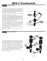
Page 15: ...es away from the front of the Chassis 27 Slide two 060 Spacer 61 over the back side of the Pin as indicated in Figure 28A Insert theArm into the Inner Front Pivot Blocks 59 60 Capture the FrontArms by placing the Front Main Block 65 marked with 0F onto the Inner Hinge Pins as shown in the illustration in Figure 28B Secure the Front Main Block by threading two 4 40 x 1 2 Flat Head Screws 151 throug...

Page 16: ...iddle of the Shock Tower in the lower four holes on either side of the Shock Tower 66 67 q 1 Attach the Front Shock Tower 69 to the Front of the Chassis 27 with four 4 40 x 3 8 Cap Head Screws 30 The Screws thread into the top most and bottom most holes surrounding the posts which stick out of the front of the Chassis 27 The Shock Tower should interlock with the posts on the Chassis There is a sho...

Page 17: ...d it into the end of the CVD Coupling q 4 Repeat Steps 1 3 for the second front CVD assembly Apply the enclosed Thread lock to the Set Screw before thread ing it into the CVD Coupling If Thread lock is not used the Set Screw will loosen during operation This will cause your car to stop running 74 75 q 1 Thread a 3 16 Ball Stud 43 into the top side of the Left SpindleArm 70 as shown in Figure 32A q...

Page 18: ... Marked with 4 R assembly 24 47 81 q 1 Attach the Left Spindle and Carrier assembly to the Left Front Arm 63 by aligning the holes in the Spindle Carrier 80 with the holes in the Front Arm Insert a 3 32 x 930 Hinge Pin 81 through theArm and the Spindle Carrier q 2 Make sure the Hinge Pin is centered between the ends of the Arm Secure the Hinge Pin by threading a 5 40 x 3 16 82 Set Screw into the b...

Page 19: ...s on the turnbuckle are lo cated towards the outside of the chassis for easier adjustment later q 1 Thread a Plastic Rod End 58 onto each end of a 1 Titanium Turnbuckle 89 Tighten both Rod Ends equally until the Tierod is the same length as the assembled Tierod in Figure 37B Make two of these assemblies Each end of the Turnbuckle is threaded opposite One end has right hand threads the other has le...

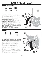
Page 20: ... Main Block it may be necessary to slightly loosen the screws in the Inner Pivots about 1 full turn Once this is done tighten the Main Block followed by tightening the Inner Pivots This will ensure you get the correct Pin angle in the Arms q 2 Position the RearArms 92 so that the Shock mount holes face away from the back of the Chassis 27 Slide a 060 Spacer 61 over each side of Inner Pins as indic...

Page 21: ...unts 96 by interlocking the post on the Body Mount with the blind hole in the Shock Tower and lining up the through holes Secure the Body Mounts by threading a 4 40 x 3 8 Flat Head Screw 31 through the Body Mount and into the Rear Shock Tower as indicated in Figure 41 31 66 67 q 1 Attach the Rear Shock Tower 95 to the Rear of the Chassis 27 with four 4 40 x 3 8 Cap Head Screws 30 The Screws thread...

Page 22: ...pling Secure all three parts by inserting a 1 16 x 7 16 solid Pin 75 through the holes in the CVD Dogbone the slots in the CVDAxle and the hole in the CVD Coupling q 3 Center the Pin in the CVD Dogbone and secure it by applying a small amount of MIP Thread Lock compound 79 to a 4 40 x 1 8 Set Screw 77 and thread it into the end of the CVD Coupling Apply the enclosed Thread lock to the Set Screw be...

Page 23: ...mblies Each end of the Turnbuckle is threaded opposite One end has right hand threads the other has left hand threads This allows the length of the rods once installed to be adjusted without removing them 58 The Foam Things are primarily for use on dusty out door tracks and surfaces Their use is left to your discretion q 1 Place a Foam Thing 85 over the Ball Stud 155 in the Rear Hub 101 Place a se...

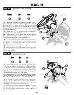
Page 24: ...ckets on the drivers right side of the Chassis q 2 Thread a 4 40 x 3 8 Cap Head Screw 30 through the bottom of the Chassis into each of the Battery Mounting Posts and tighten q 3 Peel the backing off of the Chassis Tape for the Battery 158 and align the cut outs in the tape with the appropriate places on the Chassis and apply the Tape to the Chassis as indicated in Figure 49 30 Battery Post Instal...

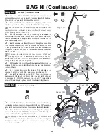
Page 25: ...of each Front Shock Shaft 156 and each Rear Shock Shaft 108 Slide a Cartridge hex end first down the Shock Shaft towards the threads as shown in Figure 51 on all four Shafts q 2 Using pliers or small vise grips grasp the Shock Shaft between the grooves and thread a Shock End 109 all the way onto the Shaft until the threads stop q 3 Repeat Step 1 2 on all four Shock Shafts q 4 Carefully snap a 1 4 ...

Page 26: ...ning with pliers or a 7 16 wrench approximately 1 8 of a turn There should be no air in the Shock as you move the Shaft in and out If there is you need more Fluid If the Shock does not compress all the way the shock has too much Fluid q 4 Repeat this for the remaining Front Shock assembly and the two Rear Shock assemblies If leaking persists around the outside tighten the Cartridge q 1 Snap a Shoc...

Page 27: ...o the Tower by threading a 4 40 Nylon Locknut onto the Shock Mount Screw q 5 Repeat Steps 1 4 for the Right Rear Shock assembly 122 123 q 1 Position the bottom of an assembled Short Front Shock in front of the Shock mounting area on the Left Front Suspension Arm 63 as shown in Figure 56 Align the hole in the Shock Mount Ball 110 with the Middle hole in theArm q 2 Secure the Shock to the Arm by thr...

Page 28: ...rly seat it into the grooves of the Wheel Make certain that the Tire Insert is not pinched between the Tire and the Wheel q 5 The Tires now need to be glued to the Wheels This can be done by using a fast curing superglue or cyanoacrylate CA glue available at your local hobby shop Team Losi Tire Glue A 7880 Thick A7881 Thin is the best glue available for gluing R C car tires This glue was produced ...

Page 29: ... in the Front Diff Cover Pre tapping these holes makes it easier to install the Screws during assembly Figure 58 30 88 q 1 Install the Rear Bumper 102 by lining up the holes in the fork of the Rear Bumper with the holes in the back of the Chassis 27 Thread two 4 40 x 1 4 Flat Head Screws 86 through the Chas sis into the holes in the Bumper as indicated in Figure 59 and tighten q 2 Thread two 4 40 ...

Page 30: ...e bottom of the Chassis The Inserts should be installed in the direction shown in Figure 61 q 2 Install the Motor Mount 127 with the motor attached in the groove on the left side of the Chassis Check alignment of the pinion gear with the Spur Gear 36 If the two Gears don t align properly remove the motor and adjust the position of the pinion gear Check again for proper alignment q 3 Once the pinio...

Page 31: ... through the bottom of the Bumper 87 into the Body Mounts 90 q 2 Slide the Foam Bumper 100 over the two Body Mount Posts with the large curved side facing away from the front of the Chassis 27 q 3 With the large curved side facing away from the front of the Chassis slide the Front Top Bumper 99 over the two Body Mount Posts down on top of the Foam Bumper q 4 Secure the Foam Bumper and Top Bumper w...

Page 32: ...f enough of the Tube so that the wire will extend about 3 4 past the end of the Tube DO NOT cut off any excess antenna wire Doing so may cause you car to glitch q 5 While pulling the wire through the Antenna Tube slide the Antenna Tube down and push it firmly into the Antenna Mount on the main Chassis q 6 Fold the wire down over the Antenna Tube and place the Antenna Cap 141 over the Tube and exce...

Page 33: ...d file to open the hole back up This will ensure your paint does not become rubbed off q 1 Make four 1 8 diameter holes Two in the areas on the Wing 149 that are marked with dimples and two in the areas marked with dimples on the wing mount stand offs at the rear of the Body q 2 Align the holes in the Rear Wing 149 with the holes in the Wing Mount stand offs at the rear of the Body Slide a 4 Washe...

Page 34: ...r should be ad justed so that the car rolls straight when you are not touch ing the steering wheel stick If the servo was installed correctly as per Tables 21A and 21B the wheels should turn equally to the left and right If this is not the case refer to Table 21B and ensure that the steering servo and rod were properly installed Make sure the throttle trim is set so that the motor does not run whe...

Page 35: ...locks that mount the inner hinge pins of the front suspension arms to the chassis You have three options with the included mounts 0 2 and 4 degrees The front is marked with a 4F and a 0F at the middle of the surface facing forward If this block is mounted with the 4F at the top there is 4 degrees of kickup if the 0F is at the top there is no kickup The other included pivot block is labeled 2F and ...

Page 36: ...rotation in the turn This might be helpful for fast flowing tracks where corner speed is critical Moving the shocks out away from the center of the tower will give more forward traction but slows the initial reaction into the turn with a more abrupt rear rotation This can be good for tight tracks Rear Camber Link Moving the rear camber link to the outside position shorter on the tower and or the i...

Page 37: ...ve you overdrive This will give the car less offpower steering and will give you more steering exiting the turn Running the 41T pulley in the rear will underdrive the car This will give you more steering entering the turn and less exiting the turn If you do mix up your pulleys you can distinguish the 41T from the 42T by looking for a ridge in the side of the flange on your 42T pulley The 41T pulle...

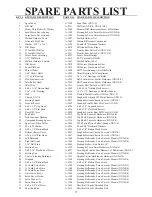
Page 38: ...4 40 x 3 8 Caphead Screws 31 4 40 x 3 8 Flat Head A 6210 4 40 x 3 8 Flat Head Screws 32 Rear Diff Cover A 9899 Graphite Front Rear Diff Cover XXX S 33 Top Shaft A 3238 Top Shaft Spacer Hardware XXX S 4 34 Belt Tensioner Bushing A 3238 Top Shaft Spacer Hardware XXX S 4 35 Compound Bearing Spacer A 3238 Top Shaft Spacer Hardware XXX S 4 36 Spur Gear Drive Pulley A 3946 90T 48 pitch Drive Pulley Oran...

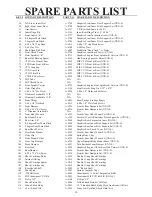
Page 39: ...inkage Rings 86 4 40 x 1 4 flat head A 6213 4 40 x 1 4 Flat Head Screws 87 Front Bumper A 4236 Front Rear Bumpers Set XXX S 88 4 40 x 5 16 Set Screw A 4236 Front Rear Bumpers Set XXX S 89 1 Titanium Turnbuckle N A N A 90 Front Body Mounts A 4229 Front Rear Body Mount Set XXX S 91 Rear Inner Pivots A 1229 Low Roll Center Rear Inner Pivot Support Set XXX S 92 Rear Arm L R A 9860 Graphite Rear Suspen...

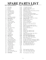
Page 40: ...utton Head A 6212 4 40 x 1 8 Button Head Screws 140 Antenna Tube A 4002 Antenna Kit 141 Antenna Tip Cover A 4003 Antenna Caps 142 Losi Hex Adapters A 3260 Wheel Hex Drives Standard Metric 143 Metric Hex Adapters A 3260 Wheel Hex Drives Standard Metric 144 8 32 Lock Nut A 6310 8 32 Locknuts 145 Droop Gauge A 9898 Graphite Droop Gauge Battery Strap XXX S 146 Assembly Wrench A 6030 Assembly Wrench Ve...

Reviews: