66
95
67
31
96
155
30
95
27
BAG E (Continued)
18
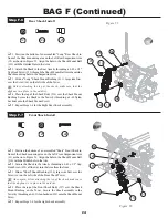
Step E-3
Step E-4
Figure 41
Figure 42
q
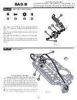
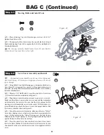
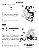
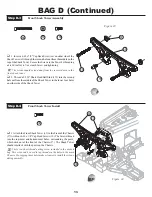
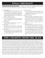
1. Thread a 0.200" Short Head Ball Stud (155) on each side of the
Shock Tower into the closest hole to the middle of the Shock Tower in
the lowest set of camber holes.
q
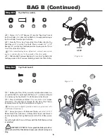
2. Insert a 4-40 x 7/8" Cap Head Screw (66) one on either side of
the Shock Tower (95) into the third hole out from the middle in the
upper set of four holes. Secure the Screws to the Tower by threading
a 4-40 Zinc Nut (67) over each Screw and tightening.
The Screws should extend away from the recessed area in the
Rear Tower and face towards the back of the Chassis.
q
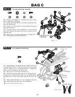
3. Install the Rear Body Mounts (96) by interlocking the post on
the Body Mount with the blind hole in the Shock Tower and lining up
the through holes. Secure the Body Mounts by threading a 4-40 x 3/
8" Flat Head Screw (31) through the Body Mount and into the Rear
Shock Tower as indicated in Figure 41.
31
66
67
q
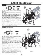
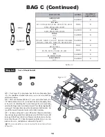
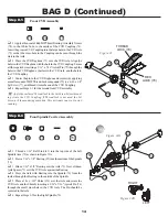
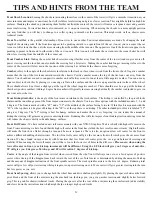
1. Attach the Rear Shock Tower (95) to the Rear of the Chassis
(27) with four 4-40 x 3/8" Cap Head Screws (30). The Screws thread
into the top-most and bottom-most holes surrounding the posts, which
stick out of the rear of the Chassis. The Shock Tower should interlock
with the posts on the Chassis.
There is a short thread-cutting screw included in the wrench
bag. This screw can be used to tap threads in the holes in the main
chassis. Pre-tapping these holes makes it easier to install the screws
during assembly.
30
Rear Shock Tower Assembly
Rear Shock Tower Install
155

