.43.
1:1
+
2 1
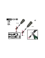
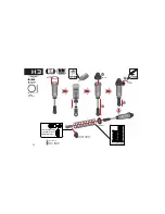
Press upper ball
into shock cap
FRONT
Note direction
1
3 2
Note smooth witness mark,
insert upper ball on this side
S T O P N U T : M 3 LO W
7 1 5 0 0 1 x 4
B H M 3 x 1 8 m m
7 0 5 0 1 2 x 2
S H O C K M O U N T
S C R E W M 3 x 2 4 m m
7 0 8 0 1 3 x 2
7 0 8 0 1 3
7 0 5 0 1 2
7 1 5 0 0 1
3 3 0 3 1 2 - 3
7 1 5 0 0 1
F r o n t S h o c k
A s s e m b l y
X
2
H4
Summary of Contents for DEX210v2
Page 1: ...DEX210 V2_Manual_Cover_Front_Final_Outlined ai...
Page 9: ...9 Assembly Instructions...
Page 12: ...12 1 1 CS M3x6mm 704004x3 704004 704004 704004 A3...
Page 18: ...18 1 1 1 1 330353 25mm 4mm BH M2 5x4mm 705029x4 705029 705029 330353 330363 1 X2 B4...
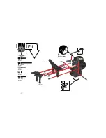
Page 30: ...30 1 1 BH M3x10mm 705005x3 705005 705005 320270 3 320270 1 F2...
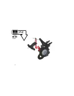
Page 31: ...31 1 1 BH M3x8mm 705002x2 705002 705002 320270 2 F2...
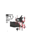
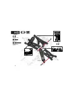
Page 37: ...37 1 1 Front Left Camber Link Front Right Camber Link Steering Link Steering Link G2...
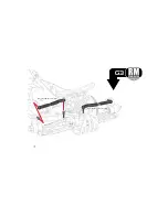
Page 38: ...38 1 1 Rear Right Camber Link RM Rear Left Camber Link RM G3...
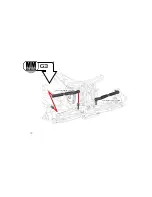
Page 39: ...39 1 1 Rear Right Camber Link MM Rear Left Camber Link MM G3...
Page 47: ...47 1 1 390298 320128 2 320128 3 320128 3 I2...
Page 49: ...49 1 1 701004 390001 390001 SETSCREW M3x3mm 701004x1 I4...
Page 50: ...50 1 1 390085 402031 390085 I5 Cut along cut line...
Page 51: ...51 1 1 390085 390085 Cut along cut line I5 402031...
Page 52: ...52...
Page 53: ...53...
Page 54: ...54...
Page 55: ...55...
Page 56: ...56 Notes...
Page 57: ...57 Notes...
Page 58: ...58 Exploded View...
Page 69: ...69 Final Assembly 390085 402031 480003 390085 390085 320126 3 320126 3 390085...
Page 70: ...70 Final Assembly 390085 390085 390085 320126 3 320126 3 390085 402031 480003...
Page 76: ...DEX210 V2_Manual_Cover_Back_Final_Outlined ai...

