background image

.2.

Inhaltsverzeichnis

ⴞ䤴

Before you begin                          

.3.

Assembly                                                    

.3.

Safety Notes – IMPORTANT       

.4.

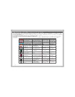
Symbol  Reference Key                     

.7.

Assembly  Instructions                    

.9.

Exploded  View                                   

.58.

Parts  List  Standard Parts                                          

.71.

Parts  List  Option Parts                                              

.72.

Team Durango Ltd                                           

.75.

僕傾僧僑


.3.

⤌❧僌๓僑䢢


.3.

Ᏻ඲僔僅僧僑䢢䯋㔜せ凕


.5.

儛兗兀兏兎儹儅児兗儝


.7.

⤌❧僌


.9.

ᒎ㛤ᅗ


.58.

儵兠儨兎儝儬


.71.

儎儻儛克兗儵兠儨兎儝儬


.72.

䣖䣧䣣䣯䢢䣆䣷䣴䣣䣰䣩䣱䢢䣎䣶䣦


.75.

Bevor Sie anfangen                          

.3.

Zusammenbau                                                   

.3.

Sicherheitswarnungen – WICHTIG       

.5.

Symbol Schlüssel                     

.7.

Montage Anleitung                   

.9.

Explosionsansicht                                   

.58.

Ersatzteileliste                                           

.71.

Tuningteileliste                                           

.72.

Team Durango Ltd                                          

.75.

㓺㻻ࢃ䈪᱄


.3.

㓺㻻


.3.

ᆿޞ亱⸛ā䠃㾷έ


.6.

䈪᱄Ҝㅜਭ䈪᱄


.7.

㍺㼓↛傕


.9.

⠼⛮ൌ


.58.

ж㡢Ԭ䴬Ԭ㺞


.71.

᭯㼓Ԭ䴬Ԭ㺞


.72.

7HDP'XUDQJR䙙㎗ؗᚥ


.75.

Contents

┠ḟ

Summary of Contents for DEX210v2

Page 1: ...DEX210 V2_Manual_Cover_Front_Final_Outlined ai...

Page 2: ...iew 58 Parts List Standard Parts 71 Parts List Option Parts 72 Team Durango Ltd 75 3 3 5 7 9 58 71 72 75 Bevor Sie anfangen 3 Zusammenbau 3 Sicherheitswarnungen WICHTIG 5 Symbol Schl ssel 7 Montage An...

Page 3: ...V VR VKRXOG RX QG DQ SDUWV GLI FXOW WR assemble please check that you are assembling them correctly If you don t follow these instructions exactly you may damage parts of your DEX210v2 If for any reas...

Page 4: ...g or making this kit This kit is designed for use on r c car race tracks It should not be used in general public areas Team Durango Ltd accept no responsibility for any injuries caused by making or us...

Page 5: ...Betrieb des Modells notwendig sind Team Durango bernimmt keine Verantwortung f r den Gebrauch dieser zus tzlichen Gegenst nde F r den einwandfreien Zusammenbau und Betrieb ist Modells ist alleinig de...

Page 6: ...6 Team Durango Team Durango Team Durango Team Durango Team Durango Ltd R C Team Durango Ltd R C R C R C R C R C...

Page 7: ...ett Silicone Grease Silikon Thread Lock Schraubensicherungsmittel Pay special attention Besondere Bedeutung 1RW QFOXGHG LQ WKLV NLW 1LFKW LP DXNDVWHQ enthalten Use double sided tape to secure Mit dopp...

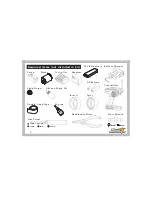
Page 8: ...ded in kit Receiver Servo Cross Wrench M3mm M4mm Controller Hex Driver 1 5mm 1 3mm 0 05inch 2mm 2 5mm Needlenose Pliers Diff and Shock Oil Battery Charger Motor AA Battery 2S LiPO battery 64dp Pinion...

Page 9: ...9 Assembly Instructions...

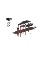
Page 10: ...10 1 1 A1 CS M3x6mm 704004x2 704006 704004 704004 704006 320215 2 320215 1 320240 704006 704006 320269 4 704006 704006 CS M3x8mm 704006x8 A...

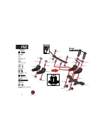
Page 11: ...BALL C TYPE 330602x3 CS M3x18mm 704001x2 BH M3x8mm 705002x2 BB 3x7x3mm 601023x4 SHIM 3x5x0 1mm 709018x4 Shim 3x6x0 5mm 709032x2 340004 340004 715001 715001 320157 330602 330602 330602 704001 705002 7...

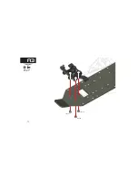
Page 12: ...12 1 1 CS M3x6mm 704004x3 704004 704004 704004 A3...

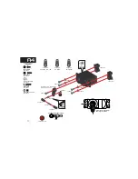
Page 13: ...shown 2mm Assemble the drag link as shown Thread Lock BH M3x8mm 705002x5 SETSCREW M3x12mm 701007x1 BH M3x6mm 705001x1 PIVOT BALL A TYPE 330033x1 Shim 3x6x0 5mm 709032x4 705002 701007 330591 1 330591...

Page 14: ...14 1 1 CS M3x10mm 704007x6 BH M3x14mm 705011x2 705011 704007 704007 704007 704007 320124 1 320124 2 705011 A5...

Page 15: ...2 CS M3x18mm 704001x4 CS M3x14mm 704005x4 Pivot Ball C Type 10mm Long 330601x2 CS M3x12mm 704003x2 704005 704005 704001 704003 704003 320123 2 320123 2 320123 1 330578 4 330598 1 330601 330363 1 33036...

Page 16: ...16 1 1 Set droop screws level with wishbone as shown 35mm 1 1 330352 BH M3x10mm 705005x2 SETSCREW M4x8mm 701010x2 705005 330352 701010 330594 1 330594 2 330348 320269 2 B2...

Page 17: ...0349 330340 3 330339 4 330339 2 Right Left STEERING KNUCKLE BUSHING 340004x4 STOP NUT M3 LOW 715001x4 BH M3x10mm 705005x2 BH M3x12mm 705004x4 Shim 3x6x0 5mm 709032x2 X2 330601 330601 330363 1 330363 1...

Page 18: ...18 1 1 1 1 330353 25mm 4mm BH M2 5x4mm 705029x4 705029 705029 330353 330363 1 X2 B4...

Page 19: ...709015 310135 330602 330340 8 601003 601017 330363 1 330339 6 310254 310113 310123 310437 Left X2 PIVOT BALL C TYPE 330602x2 Shim5x7x0 2mm 709015x4 C1 C R 1 5 R 1 R 0 5 R 1 5 R 1 R 0 5 0 LEFT RIGHT 1...

Page 20: ...1 L R 1 1 330351 37mm Set droop screws level with wishbone as shown 2mm 2mm BH M2 5x4mm 705029x4 DROOP SCREW 701001x2 701001 330351 330363 1 330363 1 330712 1 330712 2 705029 705029 Right Left X2 Rea...

Page 21: ...21 1 1 1 1 330350 41mm Thread Lock 330363 1 709032 CS M3x10mm 704007x2 PIVOT BALL A ARM 330037x2 330037 330599 330578 1 704007 330350 704006 704006 704007 C3 CS M3x8mm 704006x2 Shim 3x6x0 5mm 709032x2...

Page 22: ...cone Grease PRE COMPRESS SPRING BB 10x15x4mm 601003x2 SHIM 10x12x0 1mm 310033x4 BB 5x8x2 5mm 601020x2 SHIM 5x7x0 2 709015x1 F3 8 Caged Thrust Race 603005x1 3mm Ball 603003x14 Circlip 8x0 8mm 710002x1...

Page 23: ...23 1 1 For rear motor follow steps on left side pages For mid motor follow steps on right side pages www team durango com dex210 motor config...

Page 24: ...033x1 34T Idler Gear 310238x1 BB 5x10x4mm 601002x2 Idler Gear Pin 310247x1 BB 5x8x2 5mm 601022x1 BH M3x15mm 705003x1 Idler Gear Shim 5x8x0 5MM 709033x2 BH M3x22mm 705013x1 210033 310238 310459 1 31045...

Page 25: ...3x6x0 5mm 709032x2 BB 5x10x4mm 601002x4 Idler Gear Pin 310247x2 BB 5x8x2 5mm 601022x1 BH M3x15mm 705003x1 BH M3x22mm 705013x1 Idler Gear Shim 5x8x0 5MM 709033x4 210033 210033 310248 310459 1 310459 2...

Page 26: ...RTIGHTEN Thread Lock Shim 3x6x0 5mm 709032x3 BH M3x36mm 705026x1 BH M3x32mm 705027x2 Layshaft Spacer 5x6 5x11mm 310243x1 BB 5x11x4mm 601013x1 705027 705027 709032 709032 705026 310255 310243 601013 31...

Page 27: ...ionary there is a small amount of slip This will leave approx 2mm of exposed thread on the slipper assembly Thread Lock Shim 3x6x0 5mm 709032x2 STOP NUT M3 HIGH 715002x1 Pin 1 5 x 7mm 310239x1 310239...

Page 28: ...STOP NUT M3 LOW 715001x1 BH M3x8mm 705002x2 BH M3x15mm 705003x2 CS M3x14mm 704013x4 BH M3x30mm 705028x1 330601 330601 704013 704013 705028 320227 1 320126 1 320126 1 330598 2 715001 704013 704013 7050...

Page 29: ...n of shock tower 1 2 STOP NUT M3 LOW 715001x1 BH M3x15mm 705003x2 BH M3x30mm 705028x1 CS M3x14mm 704013x4 330601 330601 704013 704013 705028 320126 2 320126 2 330598 2 715001 705003 705003 F Pivot Bal...

Page 30: ...30 1 1 BH M3x10mm 705005x3 705005 705005 320270 3 320270 1 F2...

Page 31: ...31 1 1 BH M3x8mm 705002x2 705002 705002 320270 2 F2...

Page 32: ...07x2 CS M3x8mm 704006x2 BH M3x10mm 705005x4 SETSCREW M3x16mm 701008x2 BH M3x12mm 705004x4 704007 704007 701008 701008 704006 704006 705004 705004 705005 705004 705005 705005 705005 705004 320128 1 320...

Page 33: ...33 1 1 8mm BH M3x10mm 705005x2 SETSCREW M3x16mm 701008x2 CS M3x10mm 704007x4 320270 4 320270 4 701008 701008 705005 704007 704007 704007 704007 705005 320128 1 320128 1 F3...

Page 34: ...4 320128 4 704059 704059 704006 704007 705014 705003 705003 705014 704007 715001 704006 CS M3x10mm 704007x2 CS M3x30mm 704059x2 BH M3x15mm 705003x2 BH M3x20mm 705014x2 STOP NUT M3 LOW 715001x2 CS M3x8...

Page 35: ...35 1 1 BH M3x20mm 705014x2 CS M3x10mm 704007x2 STOP NUT M3 LOW 715001x2 CS M3x30mm 704059x2 320269 3 320128 4 705014 705014 715001 704059 704007 310459 4 F4...

Page 36: ...tely This will fully form the internal thread pattern inside your ball cup Step 3 Thread the ball cup onto the turnbuckle once again and continue until you reach the VSHFL HG OHQJWK IRU IURQW VWHHULQJ...

Page 37: ...37 1 1 Front Left Camber Link Front Right Camber Link Steering Link Steering Link G2...

Page 38: ...38 1 1 Rear Right Camber Link RM Rear Left Camber Link RM G3...

Page 39: ...39 1 1 Rear Right Camber Link MM Rear Left Camber Link MM G3...

Page 40: ...ont Rear Use correct front and rear pistons 330590 3 2x1 7mm 330590 4 3x1 7mm 705008 709009 330609 1 1 52mm 42 5mm 330596 Front 330169 Rear 330597 Front 330043 Rear 330011 3 330011 4 330011 5 330312 5...

Page 41: ...41 1 1 X2 FRONT 22 6mm REAR 32 7mm Ensure shock length is set as shown Rear Front 330591 3 330346 330034 330591 3 PIVOT BALL B TYPE 330034x2 Shock Rod End Pivot Ball 330346x2 H2...

Page 42: ...IL Front 400CST Rear 300CST M2X5 705008 13X1 330160 330600 1 Front 330600 2 Rear 330312 1 330181 Ensure the spring perch is seated between the lower ball and shock stopper BH M2x5mm 705008x4 BB SHOCK...

Page 43: ...ock cap FRONT Note direction 1 3 2 Note smooth witness mark insert upper ball on this side STOP NUT M3 LOW 715001x4 BH M3x18mm 705012x2 SHOCK MOUNT SCREW M3 x24mm 708013x2 708013 705012 715001 330312...

Page 44: ...mark insert upper ball on this side Press upper ball into shock cap 5 4 3 2 1 3 2 1 705004 708013 715001 715001 330312 3 STOP NUT M3 LOW 715001x4 BH M3x12mm 705004x2 SHOCK MOUNT SCREW M3 x24mm 708013x...

Page 45: ...10 77 9 22 9 57 9 93 10 28 8 82 9 16 9 50 9 83 8 45 8 78 9 10 9 43 7 80 8 11 8 42 8 74 9 05 7 50 7 80 8 10 8 40 8 70 7 22 7 51 7 80 8 09 6 96 7 24 7 52 7 80 6 72 6 99 7 26 7 53 6 50 6 76 7 02 6 29 6...

Page 46: ...46 1 1 Full Half BaseSetting None Drill here for DEX210v2 Line up to marks on wing Cut out 1 1 Scale Place clear wing on illustration 390085 390085 320126 3 320126 3 I1 I 480003...

Page 47: ...47 1 1 390298 320128 2 320128 3 320128 3 I2...

Page 48: ...48 1 1 705001 708005 601002 510018 510017 601002 BH M3x6mm 705001x2 BB 5x10x4mm 601002x4 NUT M4 FLANGED RIFFLED FLAT STYLE 708005x2 X2 I3...

Page 49: ...49 1 1 701004 390001 390001 SETSCREW M3x3mm 701004x1 I4...

Page 50: ...50 1 1 390085 402031 390085 I5 Cut along cut line...

Page 51: ...51 1 1 390085 390085 Cut along cut line I5 402031...

Page 52: ...52...

Page 53: ...53...

Page 54: ...54...

Page 55: ...55...

Page 56: ...56 Notes...

Page 57: ...57 Notes...

Page 58: ...58 Exploded View...

Page 59: ...704007 320124 4 709018 704004 320124 13 601023 340004 701007 330591 1 330033 705002 705002 705002 705002 709018 601023 704001 704001 715001 705002 330602 330602 330602 330591 1 704007 320124 1 709032...

Page 60: ...30339 3 330363 2 330340 3 310437 330339 5 310123 601003 709015 709032 330363 1 705004 340004 330340 10 330339 4 330363 1 330339 6 601017 330601 340004 715001 330339 1 330601 705004 330602 330340 8 310...

Page 61: ...5029 320269 2 701004 390001 330353 701008 704004 704001 330578 4 705005 704005 704005 701010 330598 1 330601 330601 320269 4 320123 2 705011 320128 2 705011 320128 3 330363 1 330363 1 704006 704006 70...

Page 62: ...62 Ball Differential 310263 601020 310033 601020 310033 310263 601003 310266 603005 710002 310417 310033 601003 705030 709015 310262 310033 310417 603003 14pcs 708012...

Page 63: ...0 715002 310459 3 310459 4 705006 310239 210033 310238 210033 310248 310248 601002 601002 601002 601022 310247 310247 310247 601002 601002 601002 709032 709015 705002 705002 705027 310459 2 704013 704...

Page 64: ...30037 705029 330351 705029 330578 1 320270 5 330363 1 320270 5 709032 310459 4 330599 330712 1 330712 2 701001 705005 705003 705003 705004 705004 705014 705005 705005 705005 705005 705005 320270 3 704...

Page 65: ...0037 330363 1 320128 1 320128 1 330350 709032 330363 1 330351 705029 705029 310459 4 330599 330578 1 320269 3 320270 4 320270 4 320270 2 705014 705014 705005 705005 705002 705003 701001 704007 704007...

Page 66: ...709009 709009 330043 330597 330312 1 330312 1 330600 2 330600 1 330136 330151 330590 4 330590 3 330011 3 330181 330181 330609 330609 330011 4 330011 5 330312 5 330027 330591 3 330591 3 330034 330346...

Page 67: ...67 708013 715001 715001 330591 2 330591 2 Front Shock Tower Assembly 330312 3 330591 2 330591 2 330129 330129 705012 601002 601002 510018 705001...

Page 68: ...68 715001 Rear Shock Tower Assembly 330343 330591 2 715001 708005 330591 4 330591 5 708013 705004 330312 3 510017...

Page 69: ...69 Final Assembly 390085 402031 480003 390085 390085 320126 3 320126 3 390085...

Page 70: ...70 Final Assembly 390085 390085 390085 320126 3 320126 3 390085 402031 480003...

Page 71: ...B TYPE 4pcs 7 6863 16 21 50 3 927 3 6 Parts Description 7 7851 8 67 0 PP SFV TD330169 BIG BORE SHOCK BODY 31mm STROKE 1pc TD330181 BIG BORE SHOCK CAP 4pcs TD330312 3 67 6 2 2 56 PP 6 6 2 67 1 2 6 7 7...

Page 72: ...CIRCLIP 8x0 8mm 4pcs 7 2 187 0 2 352 SFV 7 2 187 0 67 1 5 3 6 TD490037 DEX210 DECAL SHEET TD402031 DEX210 CAB FORWARD BODY SET Includes DECALS MASKS Parts Description Parts Description Parts List Opti...

Page 73: ...5 7 80 1 80 1 87721 SFV 2 9 7 80 1 80 7 80 187 SFV 7 80 1 80 7 80 187 SFV 2 7 80 1 80 7 80 187 SFV 5 7 80 1 80 7 80 187 SFV 2 9 TD320220 DIMEC20 CHASSIS DEX210 8mm TD320229 DIMEC CHASSIS DEX210 8mm T...

Page 74: ...I PP SFV TD330464 25 6 2 635 1 6 PP 7 6 5 6 2 9 5 1 JI PP SFV TD330465 25 6 2 635 1 6 PP 7 6 5 6 25 1 JI PP SFV TD330466 25 6 2 635 1 6 PP 7 6 5 6 25 8 JI PP SFV TD330467 25 6 2 635 1 6 PP 7 6 5 6 5 5...

Page 75: ...in Derbyshire England Gro britannien registriert Internet www team durango com support team durango com Der Inhalt dieser Bauanleitung und alles dazugeh rige Material unterstehen dem Copyright Team D...

Page 76: ...DEX210 V2_Manual_Cover_Back_Final_Outlined ai...

Reviews: