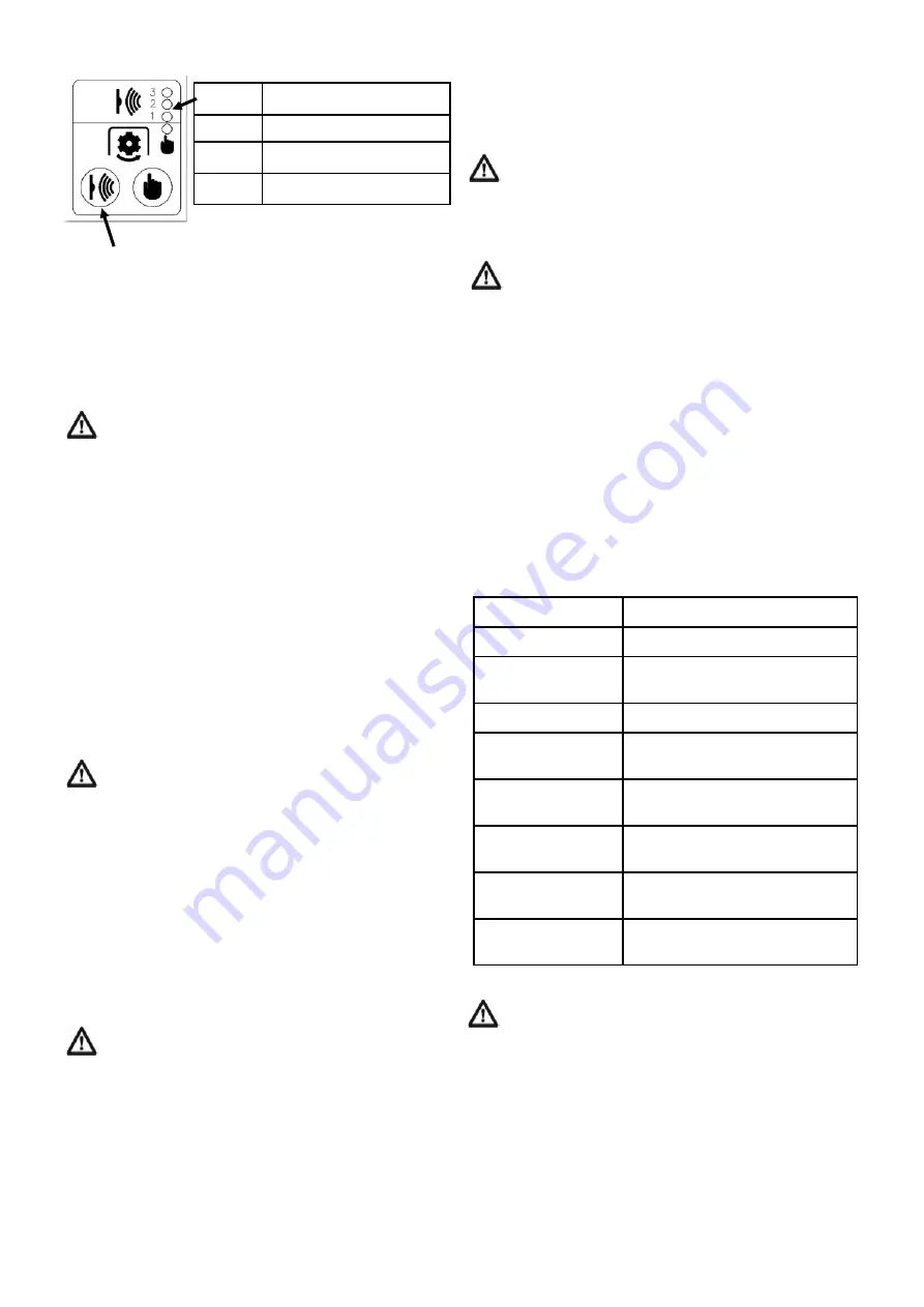
The mode is switched by repeatedly pressing the
automatic bale chamber control button.
However the optimum setting will vary depending on
material moisture content and density.
As the milled material builds up beneath the conveyor
discharge point it may be necessary to stop milling and
reposition the machine if the material can not be moved
away by the loading vehicle.
When it is necessary to stop milling part way
through a bale, always stop the bale chamber
rotation and put it in reverse for a few seconds
before stopping the mill rotor. This allows the material in
the area around the mill rotor to be removed by the
conveyor. Failure to do this may result in a blockage
when the machine is re-started.
To stop the machine without the control desk press the
auxiliary stop button on the side of the machine, this will
first stop the bale chamber rotation. After a short delay to
make sure the material is removed from the mill rotor
housing the conveyor will stop. The mill rotor will then
have to be stopped by disengaging the PTO drive in the
tractor driving the machine.
Occasionally materials may lodge against the side of the
bale chamber and not feed down into the mill. If this
occurs reverse the rotation of the bale chamber for 1 to 2
turns to dislodge the material and restart milling.
10.6 Blockage Removal
Never begin to unblock a machine until the PTO has
been disengaged, the engine stopped with the key
removed from the ignition, and the machine has
come to rest. Whilst power is connected to the machine
the red beacon will remain flashing until the rotor comes
to rest.
Should the mill rotor and housing become blocked, first
remove any material on the conveyor below the screen.
A short reverse rotation of the bale chamber is
recommended before attempting to restart the mill rotor.
Further access may be gained by removing the screen to
gain access to the rotor or by entering the bale chamber
to clear material from around the mill rotor.
10.7 Folding for Transport
Before folding the conveyor for transport ensure the
bale chamber is positioned so that the rubber stops
on the conveyor sit on the support pads on the bale
chamber. Arrows on the front of the bale chamber and
chain drive guard indicate this position.
11.0 MACHINE PROTECTION DEVICES
IMPORTANT:
The machine is fitted with a shear bolt on
the PTO shaft connecting the tractor to the machine. If
the PTO shaft is engaged harshly or after a blockage, the
shear bolt may fail and require replacement. See
paragraph 12.7 in the maintenance section.
Shearbolt
Grade 10.9
Bolt M12 x 55mm
12.0 MAINTENANCE
12.1 Safety
Never open the guards surrounding the driveline or
enter the bale chamber unless the PTO has been
disengaged, the engine has been stopped, the key
removed and the machine come to rest. Whilst power is
connected to the machine the red beacon will remain
flashing until the rotor comes to rest.
The mill rotor will take approximately 2 minutes to
come to rest from operating speed.
12.2 Lubrication and regular maintenance.
A regular visual inspection of the mill for parts showing
any excessive wear is recommended. Parts requiring
particular attention are the hammers/blades for wear and
elongation of the pivot hole. Also check the pivot rod
retaining pins are in place and there is no excessive wear
on the rods. The holes for the hammer pivot rods in the
discs of the mill rotor should be inspected for elongation
and wear.
Good quality semi-solid grease should be applied to the
grease points as shown on the relevant lubrication chart
on page 2.
The frequencies stated are hours of use.
Other maintenance points are shown in table 3 below
Table 3 Quick reference maintenance table
12.3 Wheel Changing
Serious accidents, including fatalities, have been
caused by unsafe practices during wheel/tyre
changing and when inflating tyres.
When using jacks to lift or support the machine:
a)
Use a jack capable of lifting 3 Tonnes for lifting the
machine. The jack should have a minimum height
of 470 mm and be able to extend to a length of
520 mm;
b)
Use the jacking point identified in the figure 3;
c)
Position axle stands to give additional support;
d)
Apply the handbrake to prevent movement.
10
Greasing
See separate chart on page 2
Hydraulic oil
Check oil level daily
Oil Cooler
Check / clean cooler screen
fins daily
Return line filter
Check gauge weekly
Bale chamber
chain tension
After first day then
weekly depending on use
Mill rotor belt
tension
Weekly
Hydraulic pump
drive belt tension
Monthly, depending on use
Tyre pressures &
wheel nuts
Weekly
Hydraulic oil
Analysis of oil condition
annually
3
120 - 150 (160-200)
2
104 - 120 (140 -160)
1
90 - 104 (120 -140)
Mode
Tractor power kW (hp)


