should have the speed dial set to 10 and in
Step g
you
should increase the bale chamber speed to the maximum
desired.
Important,
the oil flow for the conveyor motor is
prioritised over the oil flow to the motor rotating the bale
chamber. The speed of the conveyor should remain
constant if oil flow to the valve is reduced, as the pump
supplying the oil to the valve is driven from the milling
rotor driveline it is important the calibration is undertaken
at full working PTO speed
. The speed of the conveyor
can be changed using the thumb screw on the valve
block.
10. OPERATING INSTRUCTIONS
10.1 Screen selection
The machine is supplied with 2 half screens, different
screen sizes are available.
The size of the milled material is determined by the hole
size in the screen. It is possible to fit any combination of
screen hole size to the machine.
If a guaranteed maximum chop size is required then fitting
2 half screens with the same size holes is recommended.
If fitting half screens with 2 different hole sizes then the
smaller screen should be fitted to the right hand side of the
screen carrier frame, this screen will do the majority of the
milling. Fitting 2 screens of different sizes will allow a small
proportion of longer material to be milled. However this
may reduce milling time and power consumption.
Round hole screen sizes are available in the following
sizes 100mm, 75mm, 60mm, 40mm, 30mm, 20mm.
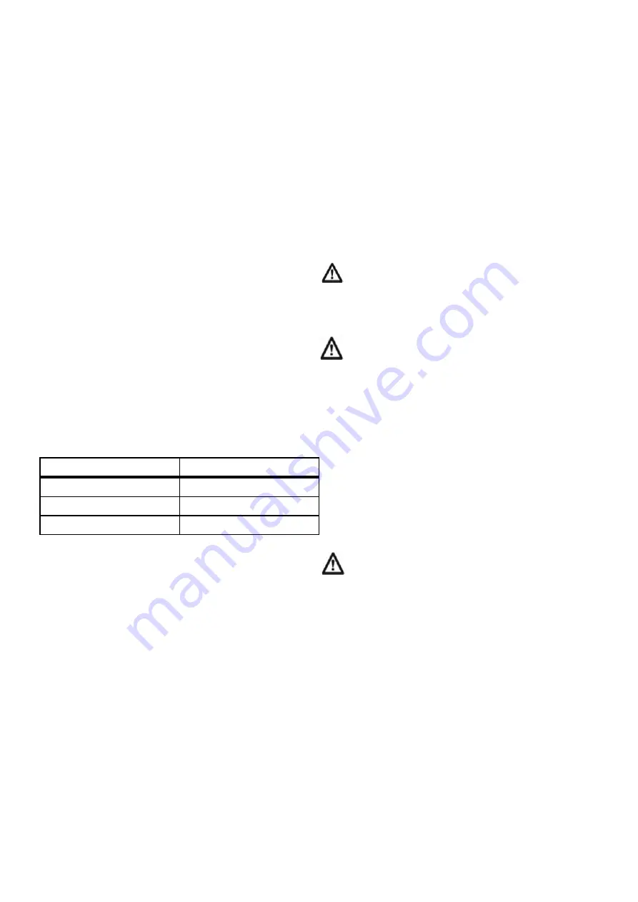
Table 2 Screen applications
Screen replacement is detailed in paragraph 12.11 in the
maintenance section of these instructions.
10.1 General
Before attempting to start and load the machine
unfold
the
conveyor from its transport position and move the machine
into its working position setting the discharge height of the
conveyor.
10.2 Starting the machine
The control desk supplied with the machine communicates
wirelessly with the electronic circuits on the machine. This
means it can be installed in the cab of either the loading
vehicle or the tractor powering the mill. Before starting the
machine, particularly if there is material in the bale
chamber, Ensure that the Bluetooth connection to the
control desk has been established and the control desk is
turned on
. This is important so that the conveyor starts
when the mill rotor starts rotating avoiding a blockage.
Select 1000 rpm PTO speed and engage the PTO shaft.
Increase the engine speed until PTO is running at
1000rpm.
Once running the rotation of the bale chamber can be
started and the rotational speed set.
10.3 Loading Machine
The strings or net should be removed from the bale before
it is loaded into the machine. The Tomahawk will mill some
string but some will tend to wrap around the rotor. Putting
twine or netwrap through the machine is not recommended
particularly where the milled material is being fed to
animals.
It is recommended that string or netwrap is removed from
the bales on the ground and then the material to be milled
loaded into the machine using a bucket or grab on the
loading vehicle.
The bale or part bale can be loaded into the bale chamber
with it rotating or by stopping the rotation of the drum, this
is easily achieved if the control desk is mounted in the cab
of the loading vehicle.
When removing string or netwrap from bales never
climb into the bale chamber unless the PTO has
been disengaged, the engine has been stopped, the
key removed and the machine come to rest. Whilst power
is connected to the machine the red beacon will remain
flashing until the rotor comes to rest.
Do not stand above the machine on a stack of bales
or in a barn to load the machine manually.
10.5 General Discharging Instructions
The speed of rotation of the bale chamber will control the
feed rate of the machine, higher rotational speeds will
result in higher processing speeds and consequently
higher power requirements. The speed of the bale
chamber is controlled by setting the speed dial on the
control desk.
When milling large rectangular bales maximum throughput
is achieved if the bale chamber is kept no less than half full
of material. The best results are achieved if part bales are
loaded into the bale chamber.
Large round bales can be placed in the tub on end or on
their side. To work out which is the best method for the
material being chopped try bales in each orientation.
Avoid dropping a complete round bale into the bale
chamber from a high level to prevent shock loading
to the mill rotor and driveline.
Ease the bale over the edge of the bale chamber and
lower into the tub as gently as possible.
The evenness of feed and power consumption will vary
with the condition of the bale. In general, damp or caked
straw materials will require a higher power input than dry
brittle materials. Bales with a moisture content greater
than
20%
will result in higher power requirements and take
longer to process & could result in blockages.
The speed of the mill rotor is monitored by the electronics,
if the mill rotor requires more power than the tractor driving
the machine is able to deliver then, as the rotor speed
drops it will reduce or stop the rotation of the bale chamber
automatically. Once the mill rotor returns to the operating
speed then the rotation of the drum will restart and
gradually return to the rotation speed set by the control
desk.
The sensitivity of the automatic bale chamber speed
control can be altered using the three modes on the
control desk. This allows the power requirement of the
machine to be varied according to the power available
from the tractor.
9
Use of milled material
Typical screen size
Long cattle feed
60, 75 &100mm
Short cattle feed
30, 40 & 60mm
Cubicle bedding
20mm


