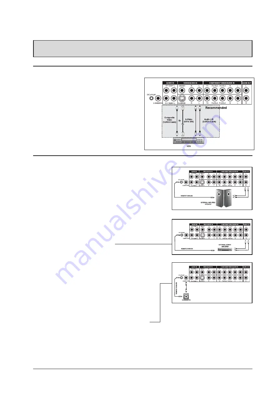
Teac PLMSDM1060 User Manual Download Page 14

11

Connecting a VCR

Using S-Video Input

1.Connect the S-Video (4-pin DIN) connector from the

VCR to the “S-VIDEO 1” input on the back of
display.

2.Connect the red (R) and white (L) audio jacks from

the VCR  to the R and L audio-in jacks located next
to the S-VIDEO 1 connector.

Using Composite Input
1.Connect the “yellow” (video) out connector from the

VCR to the yellow “Video 1” input on the back of
display.

2.Connect the red (R) and white (L) audio-out jacks

from the VCR to the R and L audio-in jacks located
next to the yellow “Video 1” connector.

CONNECTING THE DISPLAY

3.As an option, you may use the remote turn-on plug.

Please note that not all external amplified speakers can
accept remote-turn on signals.

Connecting to an External Amplifier

1.This display can be connected to an external amplifier

using the AUDIO OUT jacks located on the back of the
display.  In addition, this display is equipped with a
small 3.5 mm phono style plug for remote turn-on
applications that will automatically send a remote turn-
on/off signal to the external amplifier.

2.Connect the red (R) and white (L) AUDIO OUT jacks

from right side of the connector panel to the external
amplifier or receiver.

3.As an option, you may use the remote turn-on plug.

Please note that not all external amplifiers can accept
remote-turn on signals.

Using the Subwoofer Out (Connecting a Subwoofer)

1.This display is equipped with a subwoofer output for

connecting to an external amplified subwoofer.

2.Connect a RCA cable from the subwoofer output jack to

the external subwoofer.

Notes:

!

The AUDIO OUT RCA jacks can be set to either Fixed
or Variable audio output levels.  Please see page 23 for
additional explanation of this feature.

!

The RCA subwoofer outputs frequen-
cies below 120Hz.  The subwoofer will
use the same Fixed or Variable audio
output setting as AUDIO OUT RCA
jacks.

!

The 3.5mm phono/earphone output
level is always used for remote turn
on/off applications.

External Audio Connections

Connecting External Amplified Speakers

1.This display can be connected to an external set of amplified

speakers using the AUDIO OUT jacks located on the back of the
display.  In addition, this display is equipped with a small 3.5
mm phono style plug for remote turn-on applications that will
automatically send a remote turn-on/off signal to the external
amplified speakers.

2.Connect the red (R) and white (L) AUDIO OUT jacks from right

side of the connector panel to the external amplified speaker.

Summary of Contents for PLMSDM1060

Page 1: ......

Page 2: ...e Centre After the repair the unit will be available for collection by the owner or it will be returned to the owner The warranty does not cover freight or insurance In all cases of in transit damages...

Page 3: ...e Centre 3 Please have your purchase receipt as your proof of purchase and the following details completed for a valid Warranty Owner s Name Owner s Address Postcode Model Name No Serial No Dealer s N...

Page 4: ...ightly damp cloth for cleaning Do not place this product on an unstable cart stand or table The product may fall causing serious damage Do not place the unit on a bed sofa rug or other similar surface...

Page 5: ...SING THE DISPLAY BASICS Powering ON OFF 14 Selecting Signal Source 14 Adjusting Sound Volume 15 USING WITH HDTV Understanding HDTV 16 ADVANCEDFUNCTIONS Picture In Picture PIP Side by Side Picture POP...

Page 6: ...Reorient or relocate the receiving antenna Increase the separation between the equipment and the receiver Connect the equipment into an outlet on a circuit different from that to which the receiver is...

Page 7: ...s Cabinet Cleaning Instructions If the cabinet becomes dirty wipe the cabinet with a soft dry cloth If the cabinet is extremely dirty soak a lint free cloth in a mild detergent solution Wring the clot...

Page 8: ...nd Maximizer Built in BBE sound processor maximizes the sound quality SRS Sound Processing Built in SRS sound processor simulates sur round effects with only two speakers Selectable Fixed Variable Aud...

Page 9: ...Display Remote Control User Manual Power Cable VGA Cable Batteries Optional Accessories The following accessories are available and may be purchased from your local sales representative Wall Mount Co...

Page 10: ...ate Solid Yellow Standby Power OFF with AC power detected The LED will illuminate in yellow color if the display is shut off but the main power cord is plugged into the back of the unit Solid Green Po...

Page 11: ...end display into Standby mode Press ON to power on from standby mode See Page 14 Volume Turns volume up or down Channel UP DOWN These keys are not appli cable to this dispaly SWAP This key swaps the m...

Page 12: ...in jacks located next to the PR1 CR1 connector Using S Video Input 1 Connect the S Video 4 pin DIN connector from the DVD to the S VIDEO 1 input on the back of display 2 Connect the red R and white L...

Page 13: ...od There are two sets of component inputs provided You can use either set of component inputs to connect your HDTV Set top box Using RGB Input 1 Connect the 15 pin D Sub RGB connector from the back of...

Page 14: ...ector panel to the external amplifier or receiver 3 As an option you may use the remote turn on plug Please note that not all external amplifiers can accept remote turn on signals Using the Subwoofer...

Page 15: ...ks located to the left of the VIDEO 1 connector Notes Your PC may have audio jacks in the form of a 3 5mm phono plug If this is the case you will need to use a phono plug to RCA converter cable in ord...

Page 16: ...t select to the display in hex format 0x91 Step 2 Send 1 byte for the value of the RGB input In this example send 0x06 Step 3 The display will then respond back to the PC with a 1 byte value to confir...

Page 17: ...ressing this button will have no effect POWER Toggle Status LED Not Illuminated No AC Power detected If the main power switch rear of panel is turned off this LED will not illuminate Solid Yellow Stan...

Page 18: ...mporary basis simply press the MUTE key to silence the volume 2 When the monitor s volume is muted the monitor will display MUTE on the upper right corner of the screen 3 To disengage the mute mode si...

Page 19: ...o 480 lines in order to be displayed Progressive scan method reduces flicker however picture quality may not necessarily outperform 480 interlaced when viewed at normal viewing distances Vertical Res...

Page 20: ...o 480 lines using progessive scan format therefore resolutions higher than 480 lines must be down converted in order to be displayed This EDTV Monitor includes advanced digital process ing circuitry w...

Page 21: ...ictures SWAP 1 You can swap the main picture and sub picture using the SWAP key Press the SWAP key once to swap Press the SWAP key again to switch back Changing the Input Source for Sub Picture 1 Once...

Page 22: ...ue 16 9 aspect ratio PIP Window SWAP 1 By default the OSD will always display DISABLE To swap the main left and sub right windows use the ADJ key to swith to ENABLE Once the swap is complete the OSD w...

Page 23: ...ee the black bars when playing back a widescreen movie you can set to ZOOM 2 or ZOOM 3 to fully stretch the image 4 3 NORMAL In 4 3 mode the original 4 3 image is pre served but black bars are added t...

Page 24: ...Please note that this function is not acces sible unless the SCREEN WIDTH is set to 16 9 Widescreen Viewing Modes Con t OSD Timeout Turns on OSD timer when set to ON When set to ON the OSD will automa...

Page 25: ...ber between 1 and 120 Setting Sleep Timer Using Remote Control To set the sleep timer using the remote control 1 Press the SLEEP TIMER key on the remote This will display the sleep timer display on th...

Page 26: ...ustments Using OSD Sound adjustments are available to enhance the sound performance of the monitor These adjustments will affect the monitor s built in speakers and the AUDIO OUTPUT jacks when set to...

Page 27: ...ON to turn on the monitors internal speakers Set to OFF to turn off internal speakers This setting will not affect AUDIO OUTPUT jacks BASSEXTENSION Bass extension extends the level of BASS output by...

Page 28: ...125 50 1080i HDTV 33 0 60 1080i HDTV 45 0 60 720p HDTV When Using RGB DVI Inputs Mode Horizontal Vertical Format Refresh rate 1 31 500 59 940 640 480 VGA 60 2 37 900 72 810 640 480 VGA 72 3 37 500 75...

Page 29: ...visible COLOR Use color to adjust the color saturation of the video picture Increasing color will make the color more intense Reducing color setting will make the color less intense TINT For NTSC Onl...

Page 30: ...s will make dark areas more visible COLOR TEMPERATURE Select the color temperature for white balance There are four settings to choose from 1 LOW sets to 7180K 2 MID sets to 8680K 3 HIGH sets to 10180...

Page 31: ...h this monitor s specification section Display image doesn t fill up the full size of the screen 1 If under RGB mode the H Size and V Size is incorrectly set 2 If under AV1 AV2 or Component input the...

Page 32: ...Type Analog Polarity Positive Amplitude d Video 1Vp p with sync S VideoY 1Vp p C 0 286Vp p Frequency H 15 734KHz V 60Hz NTSC H 15 625KHz V 50Hz PAL Input impedance 75 ohms Y CB CR or Y PB PR Signal Co...

Page 33: ...640 VGA 480 60 31 500 59 940 25 175 2 640 VGA 480 72 37 900 72 810 31 500 3 640 VGA 480 75 37 500 75 000 31 500 4 640 VGA 480 85 43 300 85 010 36 000 5 800 SVGA 600 56 35 100 56 250 36 000 6 800 SVGA...

Page 34: ...nd Gross weight 101 4lbs 46 Kgs Operating Temperature 0 40o C 32 104o F Relative humidity 20 80 Pressure 800 1114hpa Non Operating Temperature 5 50o C Relative humidity 20 90 Pressure 600 1114hpa Vibr...

Page 35: ...B part 15 Power Management Mode H sync V sync Video Power dissipation Normal Pulse Pulse Active Normal power Stand by No pulse No pulse Novideo Power off Power saving Pulse No pulse blanked Less than...

Page 36: ...056 1040 1056 1048 Dots Horizontal front porch 16 24 16 56 24 40 56 16 32 Dots Horizontal sync 96 40 64 56 72 128 120 80 64 Dots Horizontal back porch 48 128 120 80 128 88 64 160 152 Dots Horiz blanki...

Page 37: ...56 476 60 023 68 677 63 981 79 976 91 146 31 469 31 469 KHz Vertical frequency 60 004 70 069 75 029 84 997 60 020 75 025 85 024 70 087 50 030 Hz Vertical sync polarity TTL Horiz sync polarity TTL Mod...

Page 38: ...MOUNT OPTION Note Follow mount bracket instruction included in mounting kit This type of equipment is to be installed by qualified installers please contact with authorized dealer for installation Re...

Page 39: ...280 William Street Melbourne VIC 3000 3 9672 2400 8 20 22 Foundry Rd Seven Hills NSW 2147 8811 4000 355 Montague Road West End QLD 4101 3010 0100 9 6522 Sir D Bradman Marion Roads way TINSE2091 1...

Reviews: