GB-4
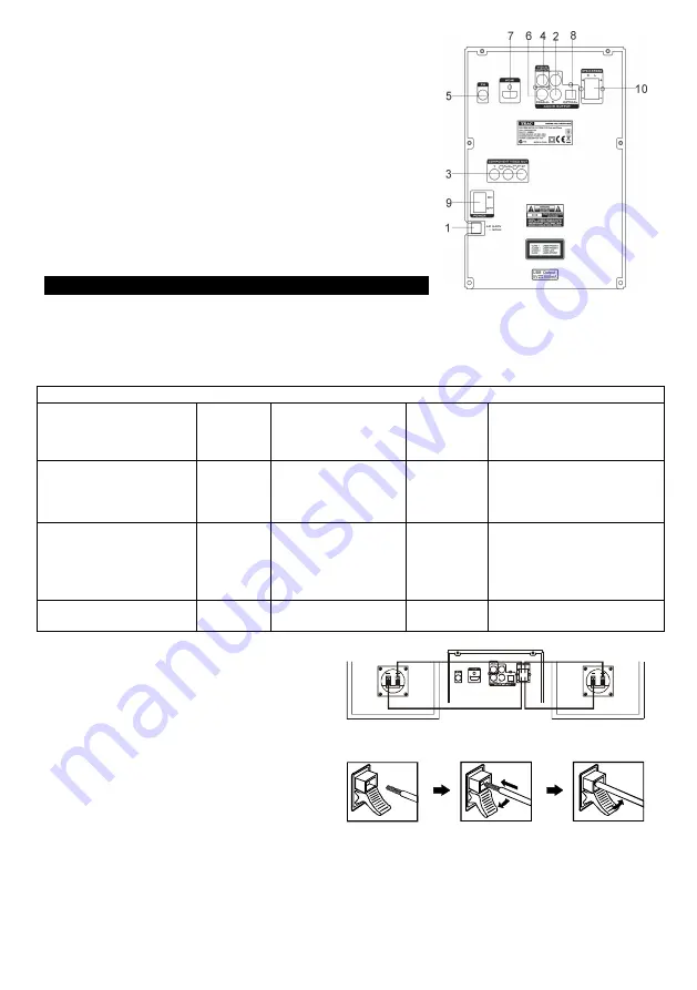
Back panel
1. Power cord
2.
L/R
(Left/Right) audio output
3. Component video output (
Y,Pb/Cb,Pr/Cr)
4. Composite
VIDEO
output
5.
FM
antenna jack
6. Digital
COAXIAL
output
7.
HDMI
output
8
.
Digital
OPTICAL
output
9.
POWER ON/OFF
switch
10.
SPEAKERS
(8
Ω
)
L/R
(Left/Right) terminals
CONNECTIONS
Connecting to a TV
The way in which the unit is connected and the kinds of cables used can make a noticeable difference in
picture and sound quality. Before selecting one of the options, please make sure that any other
equipment has the required input/output connections. Use any of the options below:
Different options for connecting your DVD player to a TV
Output(s)
Picture
quality
Cable
Cable
supplied
(Yes/No)
Video mode
(Press the
SETUP
button on
the remote control and select
VIDEO SETUP
)
Composite
VIDEO
L/R
(Left/Right) audio
outputs
Normal
A/V cable
(white+red)
Yes
VIDEO OUTPUT
–
CVBS
Y, Pb/Cb, Pr/Cr
component video
L/R
(Left/Right) audio
outputs
Very
good
Component video +
audio cable (white
+ red)
No
VIDEO OUTPUT - YPbPr
HDMI
Excellent
HDMI cable
No
HDMI SETUP
–
HDMI -
ON
Speaker connections
Connect the speakers when the unit is switched
off. This unit is designed to reproduce optimum
sound quality when the supplied speakers are
used. Connect the speaker cable with the unit to
the speaker (as shown in the diagram).
Press the speaker terminal clip down and insert
the speaker wire, then release the clip.
AUDIO IN
You can use your DVD micro system to amplify the sound from an external audio device (such as an
MP3 or CD player). To do this, connect the
AUX IN
jack on this unit to the headphones output of
external device using a 3.5 mm audio cable (not supplied). Then press the
SOURCE
button on the unit
or the
AUX
button on the remote control to select
AUX
mode.
Summary of Contents for MCDV-90i
Page 17: ......


