−
17
−
4-3 Debugging Screen Specification for the
Mechanism Controller
●
This specifications is subject to change without notice.
Indication Method of the Mechanism Controller Debugging
Screen
●
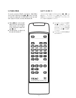
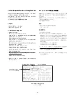
A debugging screen of the mechanism controller is indicated
when pressing the remote control unit RC-627 in order of the
ESC and CHP/TM keys.
●
Releace from debugging screen display of the mechanism
controller with the ESC key.
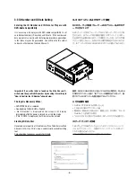
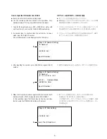
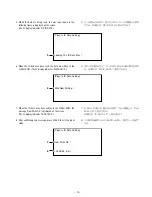
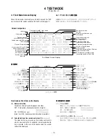
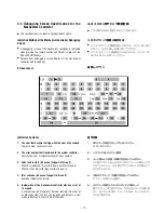
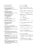
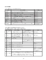
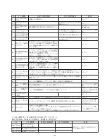
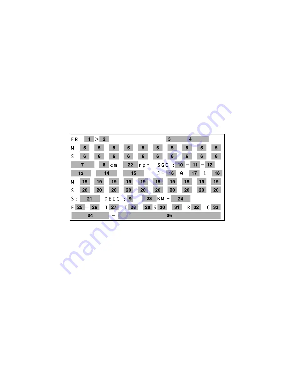
Screen Layout
4-3 メカコン用デバッグ画面仕様
●
この仕様は予告なく変更されることがあります。
メカコンデバッグ画面の表示方法
●
メカコンのデバッグ画面を表示するには、リモコンRC-627
のESC → CHP/TMキーを順に押してください。
●
メカコンのデバッグ画面表示から抜けるには、リモコンRC-
627のESCキーを押してください。
画面レイアウト
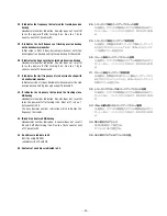
Indication Contents
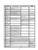
1. The error that became the trigger that an error of 2 occurred.
There are many cases same as 2.
2. The error number that transferred to the system controller
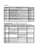
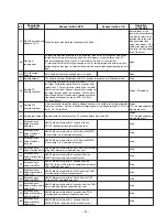
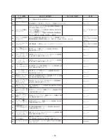
Refer to the error list about contents of error number.
3. Code read in state (it does not support in this unit)
When X is indicated, ID or subcode are not able to read in.
When X is not indicated, they are able to read in.
4. ID or subcode (it does not support in this unit)
Subcode indicates the A time.
5. Inside mode of the mechanism controller when an error of
1 occurred
It can indicate to a maximum 10 mode. Indicate it in order of
an old mode from the left, and go right, and become a new
mode. Indicate only a nest share of the mode.
表示内容
1. 2のエラーが発生するトリガとなったエラー
2と同じ場合が多い。
2. シスコンに送ったエラー番号
3. コード読みとり状態(本機では対応していません)
Xが表示されているときはID又はサブコードの読みとりが
できていないとき。Xが表示されていないときは読みとり
ができているとき。
4. ID又はサブコード(本機では対応していません)
サブコードはAタイムを表示。
5. 1のエラーが発生したときのメカコン内部モード
最大10モードまで表示できる。左から古いモードの順に表
示し、右に行くほど新しいモードになる。モードのネスト
の分だけ表示する。
Summary of Contents for Esoteric DV-50
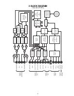
Page 5: ...2 BLOCK DIAGRAM 5...
Page 38: ...38 7 PC BOARDS AND PARTS LIST DVDM PCB SIDE A...
Page 39: ...39 DVDM PCB SIDE B...
Page 40: ...40 MAIN PCB SIDE A This PCB is a four layered board...
Page 41: ...41 MAIN PCB SIDE B This PCB is a four layered board...
Page 42: ...42 DAC PCB This PCB is a four layered board SCART PCB...
Page 43: ...43 FRONT PCB TOGGLE PCB LED PCB V UP PCB...
Page 44: ...44 OUTPUT PCB PSW PCB INLET PCB POWER PCB REG PCB...

