Energy 2510 B
Vers. 001
GB
8
3.3 Handling
The generating sets, complete with their
packaging, can be handled using common lifting
and transport vehicles.
The boxes are provided with spacers in order to
allow for the introduction of pallet truck forks.
During lifting and
transport, comply with accident prevention
and safety regulations. Use lifting and
transport equipment with a capacity greater
than the load to be lifted.
4 INSTALLATION
4.1 Preliminary information
Before installing the
generator set, it is absolutely necessary to
read these instructions to prevent any
installation errors.
The generator must be
installed so as to prevent water seeping
directly into the alternator through the air
inlets; it must therefore be protected.
Incorrect installation of generating sets can
cause irreparable damage to the equipment
and endanger the safety of users.
Should the generating sets be installed not in
compliance with the instructions in this manual,
the Manufacturer shall not be held responsible
for malfunctioning or for the safety of the
generating set, by the terms of the Italian Law
Decree D.M. 89/392/EEC. The Manufacturer
shall also not be liable for any injury or damage
to people or property.
Installation must be
performed by qualified and adequately
trained personnel only.
4.2 Instructions for fastening the generating
set
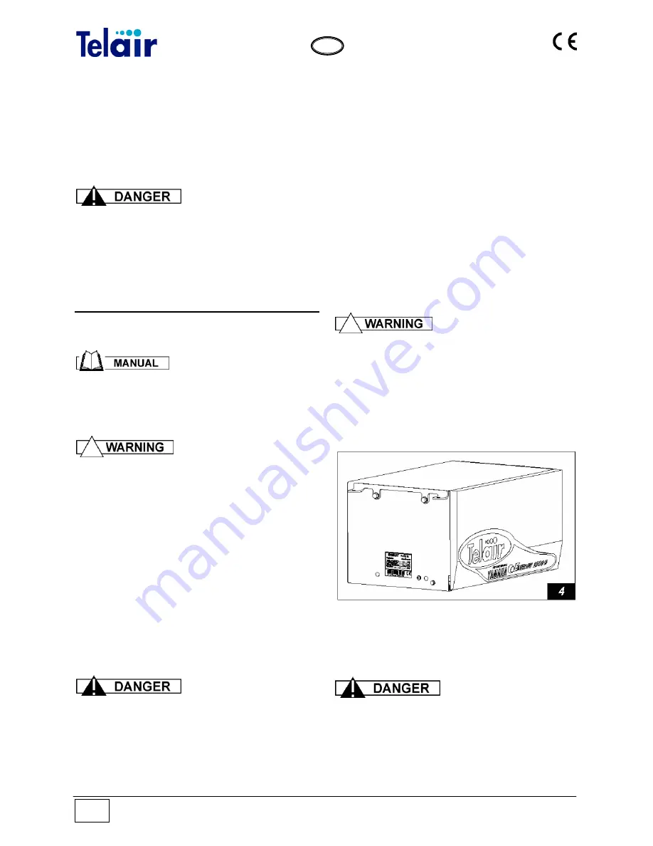
The
ENERGY 2510 B
generating sets are
provided with anchoring brackets with extra
vibration dampers
(Fig. 4, Ref. 1)
and a fuel filter
to be fitted along the generator feeding pipe. The
brackets allow for hanging and floor assembly.
This kind of assembly provides the following
advantages: less room taken up, quick
installation, easy access for routine and
unscheduled maintenance.
Make sure that there is enough room around the
hood of the generating set to let cooling air
through; also leave 10 cm free room between the
hood and the surrounding parts.
Should the generating set air intake be behind a
wheel of the vehicle,
care should be taken to
prevent water from being sprayed into the
generating set by the wheel when raining
.
Ensure that, when the door
is open, the engine sliding surface can be
taken out (Fig. 6).
4.2.1 Hanging assembly
The generator, when sticking out of the package,
is preset for hanging assembly, as shown in fig.
12.
The package also contains 4 vibration-damping
cylinders (fig. 5 ref.1) and 2 brackets for hanging
assembly (fig. 5 ref. 2).
The
vibration-damping
cylinders must imperatively be fitted as
shown in fig. 5. They must be pressed, and
NOT extended (as shown in fig. 6) by the
generator weight.
Summary of Contents for Energy 2510B
Page 29: ...Vers 001 Energy 2510 B 29 GB DRAWING FOR SPARE PARTS LIST ENERGY 2510 B ...
Page 30: ...Energy 2510 B Vers 001 30 GB ...
Page 31: ...Vers 001 Energy 2510 B 31 GB ...
Page 39: ...Vers 001 Energy 2510 B 39 GB Notes ...
Page 40: ......


