409-32048
Rev A
39
of 64
8.
‘Fiber
-
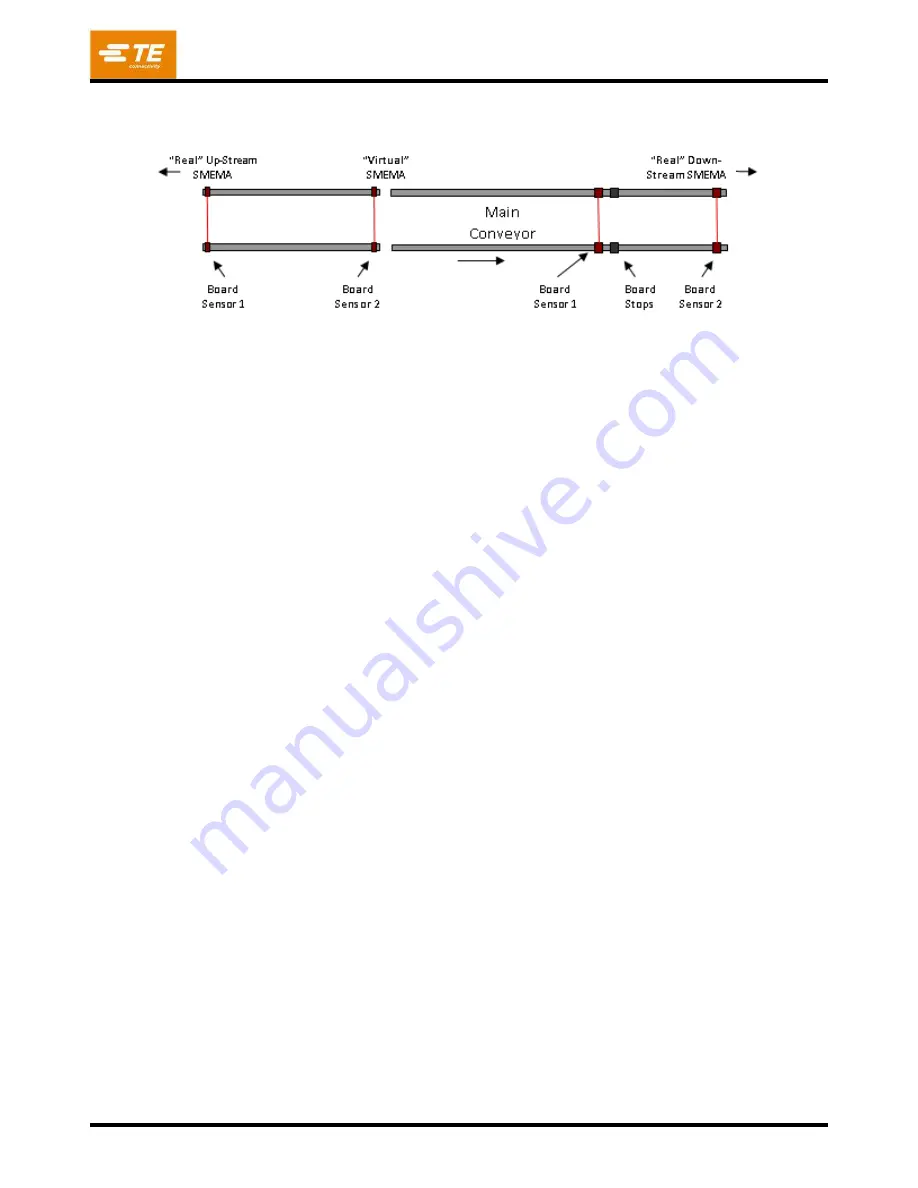
H.S. Distance’ is the distance (always in millimeters) from the thru
-beam fiber
pair “Board
sensor 1” (see Figure 40
) to the hard stops.
Figure 40
9. The main conveyor controller will bring the PCB to a stop after traveling this distance once the PCB
trips the fiber sensor beam. This value should be adjusted to cause the PCB to
lightly
contact the
hard stops during loading. This parameter is not used by the infeed conveyor. ‘Fiber
-
fiber Distance’ is
the distance (always in millimeters) between the two thru-
beam fiber sensor pairs “Board Sensor 1”
and “Board Sensor 2” on each conveyor (main or infeed). When a conveyor extension is added to
either end of the conveyor, this value must be changed since one of the fiber pairs (“Board Sensor 1”
for infeed input extension, “Board Sensor 2” for main output exte
nsion) is moved to the end of the
conveyor extension. Each conveyor controller uses this value to determine transport timeout
durations.
10.
The ‘LED High Power’ checkbox shows the current conveyor requested LED power level. The two
input indicators show the actual power level for each conveyor. High Power is required for most
PCB’s. When the conveyor rails are set very close together for narrow boards, the LED power should
be set to low to avoid saturation of the fiber sensor amplifiers. During normal operation, the LED
power level is set automatically based on the Board Width specified in the program loaded. The
maximum width to be considered a “narrow PCB” can be changed on the Setup Parameters screen, if
necessary. Note: When machine power is down, the conv
eyor controllers switch the LED’s to low
power to extend LED life. When power is restored (Machine Enable active), the LED power is set to
the requested state indicated by the checkbox.
8.5.
Setup Autoload Width
To manually adjust the Autoload conveyor width, perform the following steps. Refer to Figure 41.
1. Open the right front door on the CAPI-6T base to access the conveyor width hand crank.
2. Go to the Autoload tab on the Joystick screen to access the manual conveyor functions.
3. Use the buttons to retract the hard stops, release the clamps and lower the main conveyor.
4. Use the hand crank to open the conveyor rails wider than the desired PCB width.
5. Place a PCB onto the pressing fixture. Adjust the back conveyor rail tight against the PCB with the
hand crank, then move the rail back just enough to provide a slight clearance. The width needs to be
tight enough that the PCB cannot fall out while traversing the conveyor but loose enough to allow for
individual PCB width variation.
6. Loosen the hard stop blocks and then extend the stops. Adjust each stop block position against the
leading edge of the PCB and tighten the block adjustment screw.
7. Loosen the clamp finger screws and slide several clamp fingers over the PCB edges at even spacing.
8. Lower the clamps, then press gently down on each clamp finger and tighten the screws. The clamp
height should be such that the height limiter screws at each end of the clamp bars contact the
conveyor guide rails, all 4 clamp cylinder ‘down’ sensors are lit and the fingers are just tou
ching or
have a g
ap of 0.4mm (.015”) to the PCB.
Each clamp finger has slotted mounting holes to
accommodate different PCB thicknesses.
Forward


