

Installation Guide
eX-Series
Networked Door Controllers
To Register your Product, Visit
http://www.tdsi-product-registration.co.uk
UM0022_GB Issue 1 10/07
NOTICES
Manufacturers Details
Time and Data Systems International Ltd (TDSi)
Unit 10 Concept Park
Innovation Close
Poole
Dorset
BH12 4QT, UK
T:
+44 (0)1202 723535
F:
+44 (0)1202 724975
E:
W:
http://www.tdsi.co.uk
Sales:
+44 (0)1202 724999
Support
(UK Only):
0871 2262318
Copyright Notice
Copyright © 2007 Time and Data Systems International Ltd
(TDSi). This document or any software supplied with it may
not be used for any purpose other than that for which it is
supplied nor shall any part of it be reproduced without the
prior written consent of TDSi.
TDSi Policy
Time and Data Systems International Ltd operate a policy of
continuous improvement and reserves the right to change
specifications, colours or prices of any of its products without
prior notice.
Compliance
This product complies with the following European Directives:
Low
Voltage
73/23/EC
89/68/EC
EMC
89/336/EC
WEEE
2002/96/EC
1 OVERVIEW
Thank you for purchasing this eX-series product from TDSi. This product features a fully featured,
high quality power supply unit providing a regulated 13.8 VDC output supplying continuous full rated
current to the access control unit and locks and an additional 0.5 A for trickle charging a standby
battery. The load output features full electronic short circuit protection under mains operation.
LEDs are provided to indicate mains present and fault conditions.
For fully-detailed installation instruction, please refer to the Installation Manual on
the accompanying CD-ROM.
2
INSTALLING THE CONTROLLER
Note: It is essential to observe anti-static precautions when working inside the cabinet.
Note: This product is NOT SUITABLE for external installation and must be installed
according to all relevant safety regulations applicable to the application.
2.1 MAINS
INSTALLATION
This product must be fed from a mains power source having a separate (approved) disconnect
device and fitted with a fuse or other over-current protection device rated at 3 A maximum. Ensure
that the disconnect device used has appropriate earth fault protection to the applicable standard.
Fix the PSU to the wall or other support structure in the correct orientation i.e. with the
transformer and space for the standby battery at the bottom of the unit using the screws
supplied. Allow clearance to for the lid of the product to be fitted and removed.
Note: The
product is to be installed in an area with free air movement and with a minimum of
100 mm clearance between the sides and lid of the power supply case and any adjacent
surface (wall, ceiling or other partition).
This
equipment
MUST
be earthed.
Knock-outs (12) are provided in the case for mating with external trunking or conduit.
The mains input cable must be to the applicable standard with a 3 A or greater current
capacity, i.e. 0.5 mm
2
nominal conductor area, having a minimum operating voltage of
300/500 Vac.
The mains cable should be routed to use different entry/exit holes (4) in the case to those used
for other connected equipment (e.g. readers, locks, network cables, inputs, outputs etc.)
Grommets should be used to protect cable sheaths from chaffing. These should meet a
minimum flammability specification of UL94 HB and should be correctly sized i.e. close fitting
with respect to the cable sizing.
The mains input cable should be securely fastened to the case saddle (1) in position using a
cable tie.
2.2
INSTALLATION OF OTHER SERIVES
Refer to the tables in this guide for connection of other items e.g. readers, locks,
communications, inputs, outputs, etc.
Solder and tape all connections. DO NOT use crimps, B-connectors, wire nuts or punch-
down blocks.
All cable runs must be at least 2 m in length to allow any induced static to dissipate before it
readers the controller electronics.
The screen braid of the cables must be terminated to the earthing clamps (11) on the side
of the chassis plate unless the peripheral is connected to ground. Any portion of the
unscreened cable should be kept as short as possible and not be allowed to protrude into
the area of the electronics.
Screen braids of cables are to be connected at one end only, usually at the controller end.
Exceptions to this are if the equipment (reader, lock etc.) are metal cased and mounted on
a metal surface (such as a door frame) and in this case the screen should be connected at
the equipment end.
When
using
RS-485
It is the responsibility of the installer to follow all local and national electrical codes that may
apply.
Never install any access control system until approval has been obtained from the local fire
authority. IN particular note that the use of an exit (egress) button may not be legal.
Single-actions exit may be required.
2.3
CONTROLLERS WITH IN-BUILT ETHERNET PORTS
Some models are supplied with a Ethernet (TCP/IP) port. When installing these models, please
note the following points.
If you are connecting the eXcel
4
to an existing network, contact the network administrator to
be allocated a suitable IP address.
Before connecting the Ethernet port, reposition the 5 DIP-switches accordingly. Switch 1
should be ON (in the up position). Switches 2, 3, 4 and 5 provide RS-485 end of line
termination. Termination is required when connecting multiple controllers using RS-485
from the IP connected controller.
Note: Only one controller needs to have it’s
termination switches set for the entire RS-485 communication line.
Install the ferrite core (supplied) to the Ethernet patch lead, fitted as closely as possible to
the plug as possible (see picture below).
Connect the eXcel
4
to the network or computer, using a lead with a ferrite sleeve installed.
If there is more than one eXcel
4
, they can be connected at this stage.
Note the UID number of each controller and each unit to assist in the identification during
commissioning.
During commissioning, you may find it useful to observe the diagnostic lights on the
Ethernet port. A steady light shows that a connection exists. A flashing light shows that
there is data on that communications line (although this does not necessarily mean that this
data is directed at the controller).
For communications using a separate serial to Ethernet converter or serial to RS-485
converter, please refer to the documentation supplied with those devices.
3 COMISSIONING
Caution: Risk of explosion if the battery fitted is of an incorrect type.
Note: Dispose of used batteries in accordance with the battery manufacturer’s
instructions and to comply with all local and national regulations.
Disconnect the plug connector that supplies power to the controller circuit board.
Make the mains connection to the fused mains terminal block observing the wiring
information on the (yellow) label next to the terminal block. Ensure that the mains isolator
(disconnect device) is open.
Apply mains voltage to the input. Ensure that the green
MAINS ON
LED is illuminated.
Disconnect the mains by opening the mains isolator.
Reconnect the plug connector that supplies power to the controller circuit board.
Reconnect the mains by closing the mains isolator. Ensure that the green
MAINS ON
LED
is illuminated.
Connect the standby battery (not supplied), red cable to the +ve (red) terminal and black
cable to the –ve (black) terminal and fit the battery into the space provided.
If the battery has little or no charge, allow it to charge for a short period of time. Refer to
section
8 for battery recharge times.
Disconnect the mains by opening the mains isolator. Ensure that the green
MAINS ON
LED is extinguished and the amber
BATTERY STANDBY ON
LED is illuminated.
Reconnect the mains by closing the mains isolator. Ensure that the green
MAINS ON
LED
is illuminated and the amber
BATTERY STANDBY ON
LED is extinguished.
With the unit still powered up, remove the PCB output fuse () and ensure that the red
FAULT
LED is illuminated. Also the red LED on the distribution PCB will be extinguished.
Refit the output fuse and check that the red
FAULT
LED is extinguished and the red LED
on the output distribution board (2) is illuminated.
Ensure that the Memory Battery Link
(9) jumper is fitted.
Note all UID Numbers (10) of the controllers to assist with set-up of the controllers
Perform a final check on the security of all wiring
Close the case ensuring that all 4 lugs are located correctly in their respective cut-outs in
the case saddle.
Secure the cover in place using the screws provided.
4 OPERATING
INSTRUCTIONS
Once all connections have been correctly made, there are no further operations required. All
configuration of the door controller is achieved through either the use of eXguard eXpress or
eXguard PRO PC software. In addition, eXpert
2
master controllers allow the connection of a
local programming device to the 25-way port on the front of the controller.
The
green
MAINS ON
LED will be illuminated whilst the mains supply is present. Should
mains fail and a backup battery with sufficient charge be fitted, the amber
BATTERY
STANDBY ON
LED will illuminate. In the event of a failure, the red
FAULT
LED will be
illuminated.
5 MAINTENANCE
Note: Reference should be made to the battery manufacturer’s documentation to determine
typical/expected battery life with a view to periodic replacement of the battery.
There is no regular maintenance required other than periodic testing and replacement of the
standby battery.
If the output of the PSU fails (indicated by the red
FAULT
LED being illuminated) the cause of
the failure should be investigated e.g. short circuit load etc. The fault should be rectified
before restoring the power to the PSU. The fuses may need to be replaced. Ensure that the
replacement fuse is of the correct type and rating.
6
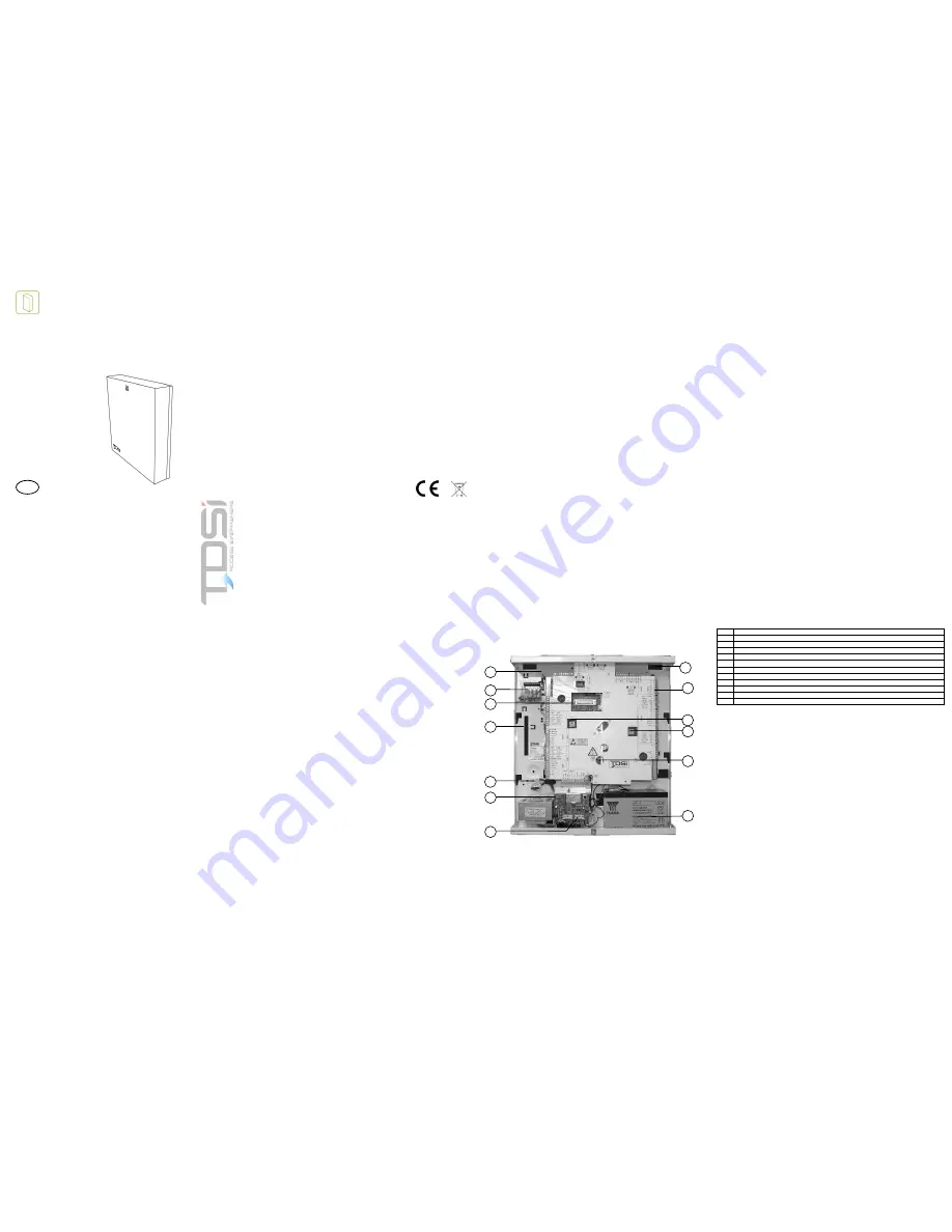
LAYOUT OF EX-SEIRES ACCESS CONTROL UNITS
The following diagram shows the layout of the controller. Please familiarise yourself with the layout
of the product before attempting installation.
Figure 1 - Layout of eX-Series (eXpert
4
Shown)
*certain models only
1 Saddle
2
Output Distribution Board and Fuses
3 Local
programming
port*
4 Cable
Entry/exit
holes
5
Fused Mains Terminal Block
6
Status Indication LEDs (green, amber and red)
7 Output
Fuse
8
Standby Battery (not supplied)
9 Memory
Battery
Link
10 Controller
UID
Numbers
11
Cable Screen Braid Earthing Clamps
12 Trunking
Knock-Out
GB
1
2
3
5
4
6
7
8
9
10
10
11
12


