CM4 App Note 260424 issue 2.1.docx
Document No. 260424
Page 28 of 29
16. Output Modules
Refer to datasheet for output module ratings
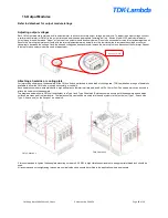
Adjusting output voltages
Each CM output module contains a built-in potentiometer to allow for accurate output voltage adjustments. To adjust the output voltage, connect
a calibrated voltmeter (or DMM) to the output terminals and insert an appropriate trimming tool (e.g. Bourns Model H-90, maximum diameter
3mm) through the hole
marked “Adjust” at the top of the output module as shown below. Do not use excessive force as this may damage the unit.
Ensure the trimming tool mates correctly with the internal potentiometer and slowly turn the tool clockwise to increase the voltage or counter-
clockwise to decrease the voltage. Once the desired voltage has been achieved, remove the trimming tool and disconnect the voltmeter. Repeat
this step for each output module in need of adjustment.
Attaching a heatsink or cooling plate
For improved performance, the baseplate of the CM4 unit can be attached to a heatsink or cooling plate. TDK-Lambda has a range of heatsinks
available to allow the CM4 to be mounted horizontally or vertically.
Each heatsink comes pre-assembled with a high performance thermal interface pad and 6 x M4 x 10mm Pozi Pan screws which can be used to
attach the heatsink to the baseplate.
The diagrams below show a CM4 unit attachment to a Type 1 and Type 2 heatsink. Before assembly ensure both the baseplate and heatsink
surfaces are clean and free from debris. The final assembly can then be mounted into the end system via the four holes (Type 1: 2 each side,
Type 2: 2 each end) on the flange of the heatsink.
It is recommended to tighten the baseplate mounting screws to 0.55 NM. In high vibration environments, an appropriate thread lock should be
used.
All recommended screw tightening torques are nominal values and should be verified in the application where appropriate.
CM4 Heatsink 1
CM4 Heatsink 2
Voltage Adjust

