User manual
3-6
DSC/DSCT Series
3.7. GETTING
STARTED
1.
Verify that the connections are well done, that the terminals are well tighten and that the correct resolver
cable is used (see par 5.1).
2.
Disconnect the power terminals of the motor.
3.
Supply the drive and after a laps of time it will appear at the display the stable term “ stop” if there are no
alarms, light blinks if there are.
4.
Configure the drive parameters: inputs (
c1
-
c5
), outputs(
c7
-
c8
), and the motor parameters, motor
current (
P56
), motor poles (
P53
), resolver poles (
P54
), ecc.
5.
Set at a low value (5%) the internal limits,
P35
,
P36
, and set to zero the velocity reference.
6.
Reconnect the power terminals of the motor and start running (L.I.2).
7.
If no alarm appears, on the display will appear the motors speed in RPM.
8.
The motor must be in stillstand the reference is digital or moving very slowly if analog.
9.
Setup the limits
P35 P36
and calibrate if necessary the speed offset with the
P4
parameter.
10.
Give some reference and verify the correct working, in particular for a correct speed and eventually tune
the controller parameters (
P23, P24
) for a better dynamical response of the drive.
11.
Execute motor cycles and see that everything is correct.
12.
Save the parameters in EEPROM.
ADVISING
: If during the operativity just explained, in particular at points 8 and 10, the motor goes over
cycles or it doesn’t move or it moves in kicking way, verify the correct execution of the electric cables.
The drive is already tuned to the motor specified at the ordering.
3.8.
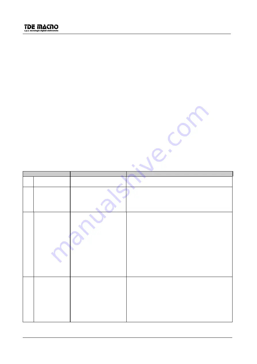
MALFUNCTIONING WITH ALARM SIGNAL : DIAGNOSIS
SAFETY ACTIVE
DESCRIPTION
REMEDIES
A1
Internal supply
error
The internal voltages are
incorrect
Check the +24V in the pin J1-9 and J1-10
A2
RAM , EEPROM
alarm
The drive reads wrong
parameter values
If the problem remains after turning on/off the drive, it
is necessary to make the C41 configuration
(reloading default values) or C42 (reloading EEPROM
values) and than use C43 (EEPROM writing). See
par. 3.5
A3
Power alarm
The output current from the
drive has reached such
levels that the saturation
control circuit of the
I.G.B.T. has intervened;
this may be caused by an
overcurrent due to
dispersion in the cables or
in the motor or to a short
circuit between the drive
output phases. Or it may be
due to a breakdown in the
regulation.
Check the connection cables particularly on the motor
side of the terminal block to remove any dispersion or
short-circuiting; check the insulation of the motor
itself, doing a dielectric rigidity test, and if necessary
replace it.
Check that the drive power circuit is working by
making it run after disconnecting the motor; if the
safety device intervenes the power circuit is
damaged.
If the safety device only intervenes during working it
could be a matter of regulation (replace it along with
the current transducers) or vibrations causing voltage
transients.
A4
Radiator thermal
switch alarm
The radiator temperature
sensor has switched on
because the radiator
temperature is too high.
Check the drive cooling circuit ; the ventilator, its feed
and the slits and filters for the entry of air into the
cabinet ; if necessary replace them or clean them
and ensure that the ambient temperature (near to the
drive) is within the permitted limits for the technical
characteristics.
If everything is in order and the alarm continues even
when the drive is cold check the connecting wires to
the thermal switch.


