background image

2800 Laura Ln, Middleton WI 53562  |  800.288.9383 Fax: 608.836.9044  |  www.tcsbasys.com  

12

INITIAL 

SETUP

These inputs must be configured using the corresponding mode objects in the internal BACnet explorer screen. See


Sec-

tion 4.5.2.6

 for more information on the internal BACnet explorer screen. For an explanation of the features listed above, 

see 

Section 5

3.5  Digital Outputs (DO)

The various control outputs required by heat and cool stage control are mapped to physical terminal blocks on the con-

troller via mechanical relays. The mapping depends on the mode of operation for the controller, and can even change 

dynamically during normal operation in heat pump mode. The relays’ terminals are described by the color of wire that is 

traditionally used for that control wire:

Figure 2

Terminal 

Designator

Color 

Function

R

Red

24V HVAC Unit Power

W

White

Heat 

Y

Yellow

Cool

G

Green

Fan

B/O

Blue/Orange

Reversing Valve

TC

n/a

Time Clock

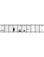
Mapping is done as shown in the table below, based on system type (conventional or heat pump), and mode of operation.

If the fourth stage of heat or cool is desired in conventional mode, then the third stage must also be enabled. 

Both of these stages are optional and must be configured using the internal BACnet Explorer.

Figure 3

Terminals (Relays)

Conventional

US4010/US4110 Only

Conventional

(Fan Powered Box)

Heat Pump 

(Normal)

Heat Pump 

(Low Limit 

Changeover)

Heat Pump 

(Emergency 

Heat)

W1

Heat 1

Heat 1

Heat 3

Heat 1

Heat 1

W2 *

Heat 2

Heat 4 

Heat 2

Heat 2

Y1

Cool 1

Heat 2

Heat 1/Cool 1

Cool 1

Y2 *

Cool 2

Heat 2/Cool 2

Cool 2

G

Fan

Fan

Fan

Fan

Fan

B/O 

Heat/Cool 3, 4 *

Reversing Valve 

Reversing Valve

Reversing Valve

TC

Heat/Cool 3, 4 *

Time Clock (TC): When used as a time clock output, this relay opens or closes based on the occupancy state. This relay 

is isolated from other heating and cooling relays, which share a common connection with the R terminal. If this output is 

used as a heating or cooling stage, the R terminal must be jumpered to one of the TC terminals. This is an open or close 

relay that will support 24V.

Reversing Valve (B/O): When the UbiquiSTAT is in heat pump mode, the B/O terminal is used as a reversing valve output. 

It may be configured as open or closed for cooling (the default is closed) via the polarity property. This can only be done 

through communications. It cannot be changed from the keypad. If the UbiquiSTAT is configured as conventional, it may 

be used as an additional heating or cooling stage. 

Summary of Contents for US4010

Page 1: ...S4120 Multi Stage RTU Thermostat US4040 US4140 Advanced RTU Thermostat US4050 US4150 Advanced Application Thermostat The UbiqiSTAT is a feature rich multifunction touchscreen thermostat which provides...

Page 2: ...Sensor Wiring 6 2 2 Remote Analog Sensor Wiring 6 2 3 Powering The Ubiquistat 6 3 Initial Setup 11 3 1 Room Temperature Sensor Selection 11 3 2 Additional Remote RTD Sensors 11 3 3 Analog Input AI Sen...

Page 3: ...SCHED I B 5 Heat Cool setpoint groups Includes all TCS SZ Series thermostat features Includes many additional features and enhancements 4 temperature inputs 1 built in 3 remote Outdoor discharge remot...

Page 4: ...ol a a Dehumidification monitoring Pressure monitoring General purpose monitoring a a Analog Outputs Hot and chilled water valve control a Modulating zone damper control w reheat a Economizer control...

Page 5: ...ld air from diffusers If using a remote room sensor the sensor should be mounted in the same manner The thermostat should be mounted in an area which is accessible for adjusting settings The UbiquiSTA...

Page 6: ...igurable as 0 20mA or 4 20mA for connecting remote sensors These inputs can be used for any current based sensors such as CO and humidity Use 18 AWG shielded twisted pair wire grounded at the sensor m...

Page 7: ...from equipment transformer 6 GND terminal is used for self powered 4 20mA inputs and outputs 3 24 VAC transformer See powering instructions 7 4 20mA transmitter sensor input wiring 18 AWG twisted shie...

Page 8: ...20mA transmitter sensor input wiring 18 AWG twisted shielded pair AI1 is shown as Self Powered sensor This input can be used for either 2 wire or self powered 3 24 VAC transformer See powering instruc...

Page 9: ...1c 1 For communication wiring use 3 con ductor twisted shielded 22 AWG 4 Dry contact Must not be powered 2 Control signals may be up to nominal 28 VAC from equipment transformer 5 For sensor input wi...

Page 10: ...onal 500ohm resistor included 1 For communication wiring use 3 con ductor twisted shielded 22 AWG 5 For sensor input wiring use 2 conductor twisted shielded 18 AWG 2 Control signals may be up to nomin...

Page 11: ...rced from an average of the internal sensor and a sensor wired to the T1 input terminals The weight of the average is also configurable and can be used to divide the input of each sensor equally Singl...

Page 12: ...third stage must also be enabled Both of these stages are optional and must be configured using the internal BACnet Explorer Figure 3 Terminals Relays Conventional US4010 US4110 Only Conventional Fan...

Page 13: ...by default where 4mA is minimum cooling damper is closed and 20mA is maximum cooling damper is open by default By default the economizer is enabled when the following conditions are met Outdoor air i...

Page 14: ...gation automatically returns to the home screen and the display dims after 10 minutes of inactivity no touches detected The basic components of the home screen are shown below Figure 4 1 Room Temp and...

Page 15: ...ame The device name is typically used describe what area or unit the thermostat is controlling The device name can only be changed using Ubiquity Cloud or an external BACnet configuration tool The tim...

Page 16: ...n the control behavior When an input value is not avail able not configured or no sensor connected dashes are displayed The following inputs are shown Room Temperature The temperature of the space zon...

Page 17: ...r Enabled Indicates whether the economizer is currently allowed to modulate open This depends on the occupancy state whether free cooling is available and if cooling is needed Free Cooling Indicates w...

Page 18: ...t Yellow The UbiquiSTAT is able to communicate but is detecting problems with the network that may cause the communication to be unreliable Check the RS 485 wiring and network configuration on other d...

Page 19: ...n Section 5 The fan proving status can be reset from the service status screen thereby re enabling system control Check Filter When a DI is configured for Check Filter service status will indicate the...

Page 20: ...setpoint pair can be used multiple times to create up to eight schedule changes per day At midnight each day the system automatically transitions to unoccupied which uses the unoccupied heating and co...

Page 21: ...0 PM Monday Store closes and cleaning crew arrives System changes to Occupied B schedule which uses the B heating and cooling setpoints 11 00 PM Monday Cleaning crew leaves System changes to Unoccupie...

Page 22: ...ry calibrated However an installation may have inherent measurement inaccuracies from sources such as sensor lead resistance and sensor placement Therefore a field calibration may be required Factory...

Page 23: ...ch explorer screen shows a single property of a BAC net object These same object properties can also be viewed over the network with BACnet network tools See the BACnet Explorer Guide for a list of al...

Page 24: ...ly An example is service status history which records any service status activity including duration Action Describe changes made to the device from a local user or an outside programming source i e U...

Page 25: ...canceled with a countdown timer shown Also the affected analog outputs are driven immediately to the appro priate Max Min levels When a test is active the manual control of relays and analog outputs i...

Page 26: ...with the analog inputs AIx AV 151 and AV 152 This is the raw input reading in milliamps AIx Scaled AV 181 and AV 182 This is the scaled representation in engineering units The units property of this o...

Page 27: ...minus the heating differential Heating turns off when the space temperature rises to the heating setpoint minus the heating offset Cooling turns on when the space temperature rises above the cooling...

Page 28: ...sible check the following System Mode Heating and Cooling Setpoints Offsets and Differentials Room Temperature is above the Cooling Setpoint or below Heating Setpoint Outdoor Air Lockout Status Discha...

Page 29: ...t for proper operation of actuators see Section 4 5 2 10 Two conditions must be met before the economizer analog output is allowed to modulate First there must be a call for cooling Second the outdoor...

Page 30: ...to the BACnet Weekly_Schedule property and the TCSbus Holiday Schedule is synced to the BACnet Exception_Schedule property of the schedule object Due to the limitations of the TCSbus holiday schedule...

Page 31: ...it is not possible to upgrade a US4040 to a US4050 7 5 Backup Restore The Backup Restore feature of Insight can backup and restore all of the user settings on the thermostat This can be useful for pr...

Page 32: ...on against harmful interference in a residential installation This equipment generates uses and can radiate radio frequency energy and if not installed and used in ac cordance with the instructions ma...

Reviews: