


R
2800 LAURA LANE • MIDDLETON, WI 53562 • (800) 288-9383 • FAX (608) 836-9044 • www.tcsbasys.com
11
ature. The built-in sensor should read 108 to 109 ohms
at room temperature. If any of the temperatures are still
reading slightly high or low, you can add in a tempera-
ture offset (calibration) using Ubiquity or TCS Insight.
In Ubiquity, you can edit the calibration offset for each
temperature input (room, discharge, outdoor air, etc.) on
the controller's programming page. For example, if the
room temperature is reading 2 degrees high, you would
subtract 2 from the existing offset in the room tempera-
ture calibration offset field and submit the page. In TCS
Insight, the process is similar. Refer to the Calibrate
Using TCS Insight Tech Bulletin # 1019 for details. As
a last resort and only when directed to do so by TCS
technical support, you may be able to use the on-
board adjustment pots. Refer to the Thermostat Sensor
Calibration Tech Bulletin # 1005 for details.
Outputs Will Not Shut Off
First check room temperature and setpoints to determine
whether the output should be on. There are delays and
minimum on and off times for the fan and heating and cool-
ing stages. Also, check the service status menus to verify
that the outputs are on. Turning the system to “off” will
instantly turn all outputs off. The thermostat can be reset
by pressing the system switch button and the service status
button simultaneously.
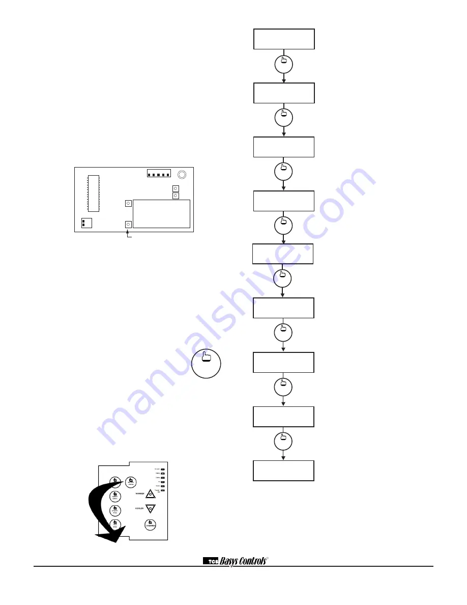
Service LED is On
If the service LED is on, it may be for
monitoring purposes or it may indicate a
critical problem. The first monitoring screen,
which is used to indicate why the light is on,
can be accessed by pressing the SERVICE
STATUS button.
SERVICE SCREENS
Through repeated pressing of the SERVICE
STATUS button, the service screens (shown below) are dis-
played, which enables you to monitor various functions of
the Superstat.
Override Status Screen.
Shows
whether the override is active and if so,
how many minutes remaining.
Stages Status Screen.
Shows the
status of the first stage of heating and
cooling.
DI1 Status Screen.
Shows the status
of DI1.
DI2 and DI3 Status Screen.
Shows
DI2 status and filter status or DI3 status.
Main Monitoring Screen.
service
status
OVERRIDE
ON
178 MINUTES
4.
service
status
HEAT STAGE 1 OFF
COOL STAGE 1 OFF
5.
service
status
DI2 OFF
FILTER
OK
7.
service
status
DI1 OK
6.
MON
12:00AM
72F
service
status
T1
T2
T3
1 2
1 2 3 4 5
adjust display contrast
service
status
Main Monitoring Screen.
Press the
service button to access the following
screens.
Service Screen.
This message may
be followed by any or all of the follow-
ing: CHECK FILTER, CHECK FAN,
DISCHARGE HIGH, DISCHARGE LOW,
or CHECK DI2.
Discharge Air Temperature Screen.
Shows discharge air temperature if sen-
sor is used.
Outdoor Air Temperature Screen.
Shows outdoor air temperature if sensor
is used.
service
status
DISCHARGE AIR
TEMP 55F
2.
service
status
OUTDOOR AIR
TEMP
75F
3.
service
status
SERVICE STATUS
OK
1.
MON
12:00AM
72F