12
DVR250-DT User Manual
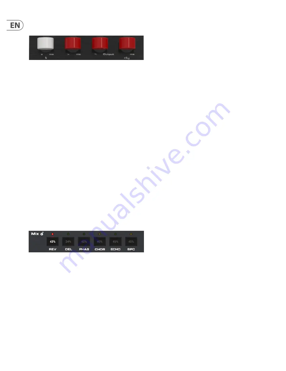
The 4 parameter slots indicate the parameters that are now available for
adjustment via the 4 levers on the hardware unit.
The levers often control certain types of parameters regardless of which effect is
selected. For example, the 4th lever always controls the predelay as long as the
primary set is active (SET button off). The first lever tends to control the primary
time parameter for each effect.
The silkscreen gives clues about the function of each lever's primary function.
Primary levers:
1. Time (t)
2. Low frequencies (>)
3. High frequencies (<)
4. Predelay (+td)
However, some of the effects deviate from this pattern. You can always check the
plug-in window if you forget the parameter mapping.
With the SET knob engaged, the first lever will always adjust the effect’s
mix parameter.
Secondary levers:
1. Mix
2. Modulation
3. Output select
4. Not used
While the Mix is always conveniently adjustable with the 1st lever when SET is
engaged, this parameter can also be adjusted on the plug-in window. Either click
and drag the mix value up or down with the mouse, or double click and enter a
specific value.
4.3.2 Reverb
The reverb effect in the DVR250 faithfully recreates a classic algorithm that has
been used on countless hit records.
Primary parameters
1.
Decay
– The main reverb decay tail is controlled by the first lever. The value
is indicated by the red LEDs on the left side of the lever scale, and range from
0.4 to 4.5 seconds.
2.
Lo Decay
– The low frequency decay time is controlled by lever 2.
The settings are indicated as multipliers of the main decay time set by lever
1, selectable between x 0.5, x 1.0, x 1.5, and x 2.0.
3.
Hi Decay
– The high frequency decay time is controlled by lever 3.
The settings are indicated as multipliers of the main decay time set by lever
1, selectable between x 0.25, x 0.33, x 0.5, and x 1.0 (max).
4.
Predelay
– Sets the amount of delay before processing takes effect,
selectable between 0, 20, 40 and 60 ms.
Secondary parameters (enable SET)
1.
Mix
– Determines how much of the processed signal is mixed with the dry
signal. A setting of 50% yields an even blend of wet and dry signals.
2.
Modulation
– Adjusts the amount of modulation in the reverb tail.
Available settings are 0%, 5%, 40% and 80%.
3.
Out Select
– Selects between the front L/R outputs and rear L/R
outputs, which have slightly different sounds on the original classic reverb
unit. The outputs can be used in a great way to create a de-correlated
quadraphonic surround reverb. This is done by using front and rear outputs
in 2 plug-in instances respectively to drive 4 output channels in total.
These could be feeding L/R front and L/R rear speakers in a 5.1 setup.
Note: If it is a stereo instance, the signal is mixed to mono before the
BASIC DELAY block.
4.3.3 Delay
The delay effect offers 4 individual clean digital echoes that are adjustable for the
left and right channels. The routing of each delay tap is arranged like this:
I: Left to left
II: Right to right
III: Right to approx. 75% to the left
IV: Left to approx. 75% to the right
Primary parameters
1.
Tap Coarse
– Sets the delay time in 20 ms increments from 0 to 300 ms for
the currently-selected tap (I-IV).
2.
Tap Fine
– Sets the fine delay time in addition to the setting of lever 1,
adjustable between 0, 5, 10 or 15 ms.
3.
Tap Select
– Selects which tap is controllable by the other
levers (I, II, III, IV).
4.
Predelay
– Sets the amount of delay before processing takes effect,
selectable between 0, 20, 40 and 60 ms.
Secondary parameters (enable SET)
1.
Mix
– Determines how much of the processed signal is mixed with the dry
signal. A setting of 50% yields an even blend of wet and dry signals. 0% mix
corresponds to setting “0.4”, 25% mix to “1.0”, 50% to “2.0”, 75% to “3.0”
and 100% to “4.5".
2.
Tap Level
– Adjusts the output level of the currently-selected delay tap,
selectable between -2, -8, -16, -120 dB.
3.
Tap Select
– Duplicate location for the Tap Select found on the primary
parameter set.
4. Lever not used.
Summary of Contents for DVR250-DT
Page 19: ......


