Chapter 4 Tutorial
T1/E1 Local Loopback Test
4-3
TC8619 Rev 1.1 User Manual
4.3
T1/E1 Local Loopback Test
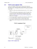
A T1/E1 Local loopback is used to test T1/E1 wiring and T1/E1 transceiver
functionality. It can be enabled by pushing both rear panel DIP switches SW1 to the
“On” (down) position. The diagram below shows the T1/E1 signal flow and related
loopback path.
1.
The “ALM” LED should be flashing indicating the unit is in T1/E1 Loopback
mode.
2.
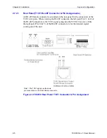
The “LOS” LED should be off indicating that a valid T1/E1 signal is being
received. If the “LOS” LED is flashing it means that the TC8619 is not
receiving a valid T1/E1 or the T1/E1 cable is in question. Please reference
Figure 2-3,
TC8619 Rear Panel T1/E1 Connector & Pin Assignment,
3.
The T1/E1 signal should be looped back to the Carrier/Service Provider or T1/
E1 tester. Please make sure a valid T1/E1 signal is being received.
4.
Upon successful completion of this test, please return dip switches
SW1(LOCLB) to the Up (Off) position for normal operation of the TC8619
unit(s).
Figure 4-1 T1/E1 Loopback Test


