Chapter 2 Installation
System Configuration
2-3
TC8619 Rev 1.1User Manual
2.7
System Configuration
The TC8619 has been pre-tested and set per factory specifications.
2.7.1
Front Panel
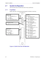
RJ48F connectors are provided on the front panel for Ethernet connections.
Figure 2-1 TC8619 Front Panel LED Definitions
T1/E1 Status
ALM (Alarm) LED
x
Solid: Latched alarm condition.
x
Flash: Unit detects errors or is in loopback mode.
x
Off: Normal
condition.
RAI (Remote Alarm Indicator) LED
x
Blink: Latched RAI indication.
x
Flash: Unit detected RAI (
Yellow Alarm
).
x
Off: Normal
condition.
AIS (Alarm Indication Signal) LED
x
Blink: Latched AIS indication.
x
Flash: Unit detected AIS (
Blue Alarm
).
x
Off: Normal
condition.
LOS (Loss of Signal) LED
x
Solid: Valid T1/E1 signal is detected.
x
Flash: No T1/E1 signal is detected.
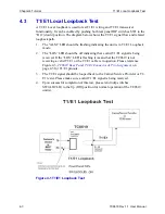
LB (T1/E1 Loopback) LED
x
Flash: Local loopback is enabled or received
CSU loop-up code.
x
Off: Normal
condition.
BPV (Bipolar Violations) LED
x
Blink: Latched BPV error indication.
x
Flash: Unit detected bipolar violations.
x
Off: Normal
condition.
CRC (T1/E1 CRC Error) LED
x
Blink: Latched CRC error indication.
x
Flash: Unit detected CRC error.
x
Off: Normal
condition.
SYNC (Loss of Frame) LED
x
Solid: T1/E1 sync. (Normal condition)
x
Blink: Latched T1/E1 sync loss indication.
x
Flash: Unit detected T1/E1 sync loss.
Ethernet Port Status
D (Duplex) LED
x
On: Full
Duplex.
x
Off: Half
Duplex.
L (Link / Activity) LED
x
On: Link
Up.
x
Flash: Activity Detected
x
Off: Link
Down
PWR (Power) A LED
PWR (Power) B LED
x
On:
Power supplied is good.
x
Off:
Power supply failed, or card fuse is
burned.
Vcc LED (Voltage) LED
x
On:
5V DC is good.
x
Off:
No 5V DC is supplied to this card.
CLEAR ERROR (T1/E1) Button
x
Press and Hold (> 3 secs) to clear latched T1/E1
error.


