

XT60
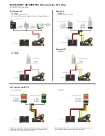
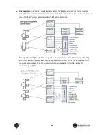
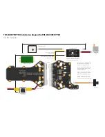
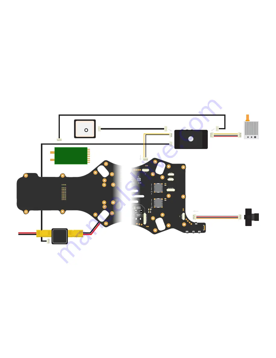
TBS CORE PNP PRO installation diagram for TBS DISCOVERY PRO
VTX
8 7 6 5 4 3 2 1
- + S
PPM Gimbal
Bott
om link
IMU/GoPro
Roll
Pitch
VTX
CAM
5V 12V
5V 12V
A
udio
Video
Gnd
Pwr
Pwr
Gnd
A
udio
Video
GP Out Sel
VTX2 Switch
Vb
at
Gnd
Video
VTX2
Gnd
Vcc
Rx
Tx
UA
RT
Gimbal
EzUHF RSSI Link
Gimal Roll
Gimbal Pitch
Gimbal PPM
Camera switch
Analog RSSI
Flight controller PPM
Pilot camera
TBS CORE
PNP PRO
CAM
BST
RSSI
BST
VTX
LINK
B-PWR
USB
UP ENTER DN
Current sensor
1 2 3 4 5 6 7 8
S + -
RSSI_ANALOG
CAM_SWITCH
GIMBAL_PITCH
GIMBAL_ROLL
PPM
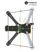
DISCOVERY
PRO
ENTR
DWN
UP
Gimbal cal
.
XT60
XT60
PWR
IN
BST
PWR
OUT
Bott
om pla
te
Top pla
te
From battery
TBS CORE PNP PRO unit
Note: no power or audio lead
(available separately)
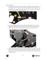
Caution: do not use the normal CAM-cable to
connect the CORE PRO to the DISCOVERY PRO
(two voltage sources conflict)
XT60
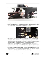
Note: mount unit in center of the bottom
plate, on top of the flight controller (NAZA),
or on the left side on the bottom plate
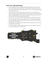
Sept. 2014 - by ivc.no/tbs
Note 1: disable the on-board DISCOVERY PRO
OSD in the CORE menu using the buttons on
the top plate - else the OSDs will overlap.
CH1
CH2
CH3
CH4
CH5
CH6
CH7
CH8
EzUHF receiver (if used)
GPS module (optional)
Note 2: the pilot camera and GoPro HD camera
switching is still performed by the on-board
TBS DISCOVERY PRO CORE.
Note 3: since there are now essentially two
COREs, you can solder the jumper on the GoPro
adapter board to enable charging at 1A rate.
Note 4: to save weight and bulk, consider
removing the plastic case for the current
sensor and connectors on one or both sides.
Left side
Existing battery lead


