
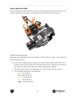
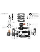
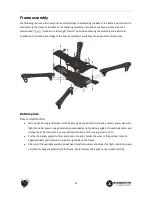
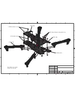


Gimbal assembly
The gimbal screws use 1.5mm (M2), 2.0mm (M2.5) and 2.5mm (M3) hex screwdrivers. Keep the screws loose at
the start and fully tighten them at the end of the assembly, this makes it easier to align all the parts. For a good
secure fit, use a very small amount of light/medium strength threadlock on all metal-to-metal-screws.
●
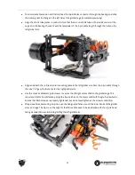
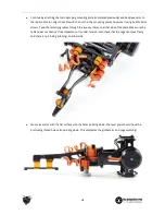
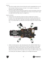
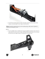
Begin by putting on the gimbal motors on the gimbal arm and black plate. For the tilt/right motor, make
sure to align the motor cable so it protrudes hidden behind the inner side of the mount. Mount it with
4x M3x4mm hex screws. For the roll/rear motor, orient the motor so that shaft/cable is pointing away
from the back mounting plate. Here, use 4x M2.5x6mm screws. Take note of the four adjustable
mounting holes on the roll/rear motor, use these to balance the GoPro at the end of the build.
●
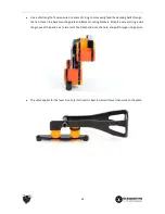
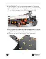
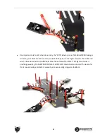
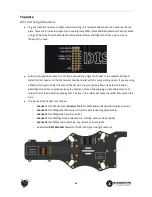
Connect the 5-pin Molex connector to the TBS IMU (Inertial Measurement Unit) board and feed the
cable through the hole on the top gimbal cage plate. Align it with the two holes and use 2x M2.5x6mm
screws to secure it.
●
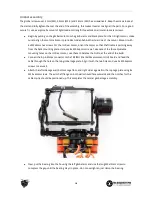
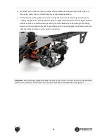
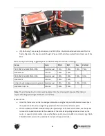
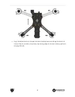
Attach the left side cage wall, bottom cage floor, and right side cage wall to the top cage plate using 8x
M2.5x6mm screws. The axis shaft flange on both walls should face outwards and the notches for the
cable zip-tie should be positioned up. This completes the central gimbal cage assembly.
●
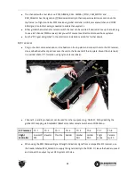
Next, put the bearing into the housing the left gimbal arm and use the long M2x12mm screw to
compress the gap until the bearing stays in place - do not overtighten, just clamp the bearing.
16


