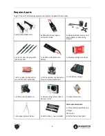

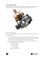
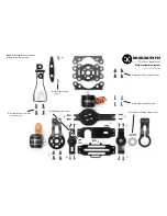
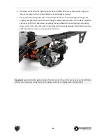
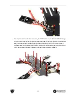

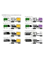

●
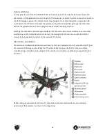
To minimize cable tension and friction, feed the 5-pin Molex connector through the bearing and slide
the bearing over the flange on the left side of the gimbal cage (completed previously).
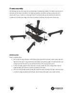
●
Align the shrink tube pieces in such a fashion that there is no shrink tube on the inside corner of the
cage or in the bearing channel. Feed the remainder of the 5-pin cable length through the hole on the
left gimbal arm.
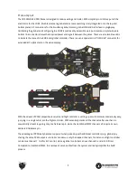
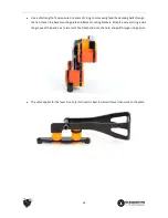
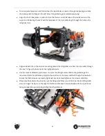
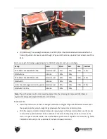
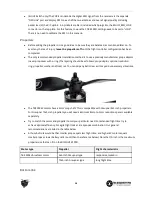
●
Align and attach the roll/rear motor mounting plate to the left gimbal arm. Pass the 5-pin cable through
the inner “U”-gap. Do the same for the right gimbal arm.
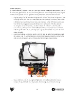
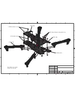
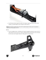
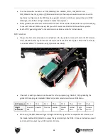
●
Use the small 2x M2x6mm grub screws to secure the tilt/right motor shaft to the gimbal cage. This
requires a 0.9mm hex (Allen) key. Align the two notches on the motor shaft with the grub screw holes.
Ensure that both screws are properly tightened, but do not overtighten as the screws could strip.
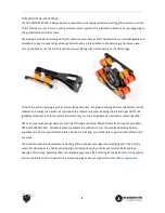
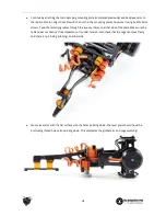
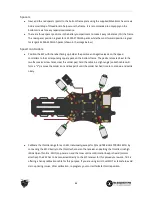
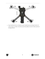
●
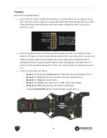
Strap down the cables using 4 zip-ties, use the designated holes around the inner bends of the gimbal
arms and cage. The zip-tie on the cage for the IMU cable needs to be positioned with the zip-tie head
facing backwards to avoid binding/hitting the left gimbal arm.
17


