


Brakes
Page 60
R-380 DC System
MR-380-03
This section is one section of a complete service
manual. Before starting any procedure, read all
warnings and instructions that are located in the
Service Guidelines chapter.
WARNING
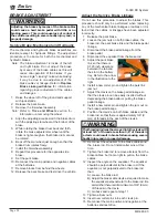
REAR DRUM BRAKE, INSPECT/
REPLACE
Note: It is recommended that both the left and right
brake pads be replaced as a set.
Service Limits
Refer to the table at the end of this section
Inspection
1: Raise the rear of the vehicle and support with
jack stands.
2: Remove the rear wheels.
3: Measure the brake lining (not including the metal
backing plate) of each shoe at it’s thinnest point.
If any one of the shoes are equal to or less
that the service limit then all shoes should be
replaced.
4: Measure the drum inner diameter in three places.
If the diameter is less than the service limit then
the drum must be replaced.
5: Lower the vehicle.
6: Reconnect the battery, remove the blocks from
behind the wheels and test drive.
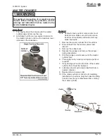
Brake Adjuster Assembly
Do not allow grease to contact any of the braking
surfaces. Braking surfaces contaminated with grease
may cause the brakes to fail resulting in property
damage and/or severe bodily injury.
WARNING
Replace
1: Release the park brake.
2: Raise the rear wheels off of the ground and
support with jack stands.
3: Remove the tire/wheel assembly. Refer to
Tires
and Wheels
section for information on removing
the wheel.
4: Remove and inspect the brake drum. Refer
to
Inspect the Service Brake
section for
information regarding inspecting the brake drum.
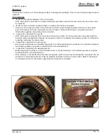
5: Remove the retracting springs and torsion springs
from the brake shoes.
6: Remove the hair pin clips from the actuating arms
and discard.
7: Remove the brake shoes and brake adjustor
assembly from the backing plate.
8: Thoroughly clean and inspect the adjustor
assembly. Replace parts as required.
9: Apply a
very light
coating of high temperature
grease to the adjustor screw threads.
10: Install in reverse order.
11: Repeat for the opposite side.
12: Adjust the brakes. See
Adjust the Service
Brakes
section for information regarding
adjusting the brakes.
13: Set the park brake.
14: Reconnect the main positive and negative at the
batteries.
15: Lower the wheels to the ground.
16: Remove the blocks from behind the wheels.
17: Release the park brake and test drive the vehicle.
Summary of Contents for R0-380-36
Page 6: ......
Page 12: ...Page 12 MR 380 03 Introduction R 380 DC System Notes...
Page 21: ...Table of Contents Special Tool List Special Tool List Troubleshooting Guide 23...
Page 24: ...Tool List Page 24 R 380 DC System MR 380 03 Notes...
Page 27: ...Lubrication Page 27 MR 380 03 R 380 DC System LUBRICATION DIAGRAM...
Page 28: ...Lubrication Page 28 R 380 DC System MR 380 03 Notes...
Page 44: ...Drive Axle Page 44 R 380 DC System MR 380 03 Notes...
Page 53: ...Steering Page 53 MR 380 03 R 380 DC System Exploded View of Steering Gear...
Page 72: ...Drive Motor Page 72 R 380 DC System MR 380 03 Notes...
Page 90: ...Tires Wheels Page 90 R 380 DC System MR 380 03 Notes...
Page 102: ...Replacement Parts Page 102 MR 380 03 R 380 DC System AXLE ASSEMBLY FRONT...
Page 104: ...Replacement Parts Page 104 MR 380 03 R 380 DC System AXLE REAR...
Page 106: ...Replacement Parts Page 106 MR 380 03 R 380 DC System BATTERY...
Page 108: ...Replacement Parts Page 108 MR 380 03 R 380 DC System BRAKES BRAKE LINES...
Page 114: ...Replacement Parts Page 114 MR 380 03 R 380 DC System BRAKES PARK BRAKE LINKAGE...
Page 118: ...Replacement Parts Page 118 MR 380 03 R 380 DC System CAB DOORS...
Page 136: ...Replacement Parts Page 136 MR 380 03 R 380 DC System STEERING LINKAGE...
Page 142: ...Replacement Parts Page 142 MR 380 03 R 380 DC System Notes...
Page 143: ......


