


Brakes
Page 59
MR-380-03
R-380 DC System
Parking Brake, Mechanical Brakes
Trucks equipped with mechanical drum brakes do not
have a separate adjustment for the parking brake. If
the parking brake requires adjustment, then the entire
brake system is in need of adjustment. Refer to
Adjust
the Service Brake
section for information regarding
adjusting the brakes.
Parking Brake, Hydraulic Brakes
Note: The service brake must be properly adjusted
before attempting to adjust the parking
brake. Refer to Adjust the Service Brakes for
information regarding adjusting the service
brakes.
Do not use this procedure to adjust the brakes. This
procedure should only be performed when replacing
any of the mechanical brake linkages or cables or it is
found that the cables or linkages have been adjusted
incorrectly.
1: Release the park brake.
2: Loosen the jam nuts on both brake cables, the
brake rod, the park brake link and the brake pedal
linkage.
3: Disconnect the equalizer from the brake rod.
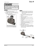
4: Adjust the park brake
link so that there is
0.125 (3 mm)inch
clearance between
the tab and the slot in
the battery tray. Refer
to the arrow in the
illustration to the right.
5: Install a new cotter pin
and tighten the park
link jam nut.
6: Position the clevis’s on both brake cables and the
brake rod so that there is approximately 3/8” (9
mm) of threads in the each of the clevis’s.
7: Reconnect the equalizer to the brake cables and
the brake rod. Do not install cotter pins at this
time.
8: Tighten the brake rod to remove all slack from the
brake cables, but not so tight to pull on the brake
cables.
The threaded rod must be screwed into the clevis with
at least 3/8” of threads. Less than 3/8” of threads in
a clevis could result in brake failure causing severe
bodily injury and/or property damage.
WARNING
9: Inspect the angle on the equalizer. The equalizer
should be perpendicular to the brake rod. If the
equalizer is not perpendicular to the brake rod
then:
A) Loosen the brake rod.
B) Adjust the brake cable clevis as required to make
the equalizer perpendicular to the brake rod. Be
certain that there is still a minimum of 3/8” (9 mm)
of threads in the clevis.
C) Go back and repeat at step 8.
10: Tighten all jam nuts.
11: Insert new cotter pins into each clevis pin.
12: Set the park brake.
13: Reconnect the main positive and negative at the
batteries, remove the blocks from the wheels,
and test drive.
Summary of Contents for R0-380-36
Page 6: ......
Page 12: ...Page 12 MR 380 03 Introduction R 380 DC System Notes...
Page 21: ...Table of Contents Special Tool List Special Tool List Troubleshooting Guide 23...
Page 24: ...Tool List Page 24 R 380 DC System MR 380 03 Notes...
Page 27: ...Lubrication Page 27 MR 380 03 R 380 DC System LUBRICATION DIAGRAM...
Page 28: ...Lubrication Page 28 R 380 DC System MR 380 03 Notes...
Page 44: ...Drive Axle Page 44 R 380 DC System MR 380 03 Notes...
Page 53: ...Steering Page 53 MR 380 03 R 380 DC System Exploded View of Steering Gear...
Page 72: ...Drive Motor Page 72 R 380 DC System MR 380 03 Notes...
Page 90: ...Tires Wheels Page 90 R 380 DC System MR 380 03 Notes...
Page 102: ...Replacement Parts Page 102 MR 380 03 R 380 DC System AXLE ASSEMBLY FRONT...
Page 104: ...Replacement Parts Page 104 MR 380 03 R 380 DC System AXLE REAR...
Page 106: ...Replacement Parts Page 106 MR 380 03 R 380 DC System BATTERY...
Page 108: ...Replacement Parts Page 108 MR 380 03 R 380 DC System BRAKES BRAKE LINES...
Page 114: ...Replacement Parts Page 114 MR 380 03 R 380 DC System BRAKES PARK BRAKE LINKAGE...
Page 118: ...Replacement Parts Page 118 MR 380 03 R 380 DC System CAB DOORS...
Page 136: ...Replacement Parts Page 136 MR 380 03 R 380 DC System STEERING LINKAGE...
Page 142: ...Replacement Parts Page 142 MR 380 03 R 380 DC System Notes...
Page 143: ......


