


Steering
Page 51
MR-380-03
R-380 DC System
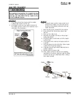
STEERING GEAR
Disassemble
Note: The steering gear must be removed from the
vehicle for this procedure. Refer to Replace the
Steering Gear section for information regarding
removing the steering gear.
Note: The steering gear is packed with grease. Only
perform maintenance on the steering gear in an
area that will contain any grease that may spill
out of the steering gear when it is disassembled.
Refer to the illustration at the end of this section for an
exploded view of the steering gear assembly.
1: Center the steering gear.
a. Turn the steering shaft all of the way in one direction.
b. While counting the rotation, turn the steering shaft all
of the way in the opposite direction.
c. Turn the steering shaft 1/2 the number of turns in the
original direction.
2: Remove the worm bearing adjuster locking ring and
the worm bearing adjuster.
3: Remove the side cover/pitman shaft assembly by
removing the three side cover bolts and then pulling
the assembly out of the housing.
Note: The side cover/pitman shaft assembly normally
does not have to be disassembled.
4: Remove the worm shaft and ball nut assembly from
the bottom of the housing.
5: Remove the worm shaft seal.
6: Remove the pitman shaft seal.
7: Remove the upper worm bearing and bearing cup
from the housing.
8: The ball nut assembly consists of two sets of ball
bearings that recirculate in two channels in the ball
nut housing. The bearings may fall out once the
bearing guides are removed. Be careful not to lose
any of the bearings.
9: Remove the ball guide clamps, ball guides and all of
the ball bearings.
10: Remove the ball nut from the worm shaft.
11: Thoroughly clean and inspect all parts for signs of
corrosion, damage or wear and replace as required.
This section is one section of a complete service
manual. Before starting any procedure, read all
warnings and instructions that are located in the
Service Guidelines chapter.
WARNING
Summary of Contents for R0-380-36
Page 6: ......
Page 12: ...Page 12 MR 380 03 Introduction R 380 DC System Notes...
Page 21: ...Table of Contents Special Tool List Special Tool List Troubleshooting Guide 23...
Page 24: ...Tool List Page 24 R 380 DC System MR 380 03 Notes...
Page 27: ...Lubrication Page 27 MR 380 03 R 380 DC System LUBRICATION DIAGRAM...
Page 28: ...Lubrication Page 28 R 380 DC System MR 380 03 Notes...
Page 44: ...Drive Axle Page 44 R 380 DC System MR 380 03 Notes...
Page 53: ...Steering Page 53 MR 380 03 R 380 DC System Exploded View of Steering Gear...
Page 72: ...Drive Motor Page 72 R 380 DC System MR 380 03 Notes...
Page 90: ...Tires Wheels Page 90 R 380 DC System MR 380 03 Notes...
Page 102: ...Replacement Parts Page 102 MR 380 03 R 380 DC System AXLE ASSEMBLY FRONT...
Page 104: ...Replacement Parts Page 104 MR 380 03 R 380 DC System AXLE REAR...
Page 106: ...Replacement Parts Page 106 MR 380 03 R 380 DC System BATTERY...
Page 108: ...Replacement Parts Page 108 MR 380 03 R 380 DC System BRAKES BRAKE LINES...
Page 114: ...Replacement Parts Page 114 MR 380 03 R 380 DC System BRAKES PARK BRAKE LINKAGE...
Page 118: ...Replacement Parts Page 118 MR 380 03 R 380 DC System CAB DOORS...
Page 136: ...Replacement Parts Page 136 MR 380 03 R 380 DC System STEERING LINKAGE...
Page 142: ...Replacement Parts Page 142 MR 380 03 R 380 DC System Notes...
Page 143: ......


