6
11
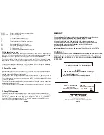
Fig.2 Control panel view
1. Text display
2.
Increase button
3.
Choice button of parameter
4.
Decrease button
5.
Confirm button
6.
Power button
7.
Status lamp of the regulator: emergency(red), standby (orange), operation (green)
8.
Lamp of pumps operation
9.
Lamp of throttle operation (blinking means the overload of the drive)
3.1 Time zones
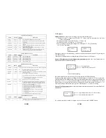
The regulator is equipped with the clock, which enables the automatic change of the regulator
operation at different times of day. 24 hrs are divided into 3 time zones (
$1, $2, $3
) and the single time
when no zone is active that is ZONE 0 or BAZA (BASE). Each zone has a start time (OD)/FROM
and an end time (DO)/TILL.
For the regulator factory settings are as it follows:
ZONE 1
FROM 6.00 TILL 8.00
ZONE 2
FROM 14.00 TILL 17.30
ZONE 3
FROM 20.00 TILL 22.30
Demonstration change of the “Mode OFF” parameter
defining the throttle position in power-
off state (parameter of level 3):
Press:
repeatedly “CHOOSE” button till the “Menu 0” parameter setting screen appears
„CONFIRM” button > „0” starts blinking
threefold button ”+” -> „3” blinks
„CONFIRM” button -> „3” stops blinking (Parameters of level 3 were chosen)
„CHOOSE” button -> „Ti.Pause xx” shows up
(The value of the „
Ti.Pause
” parameter )
„CHOOSE” button -> „ModeOFF” shows up(actual value)
„CONFIRM”button -> actual value to be changed begins blinking
„+”/”-„ -> setting a new value
„CONFIRM” -> confirming the new value
repeatedly “CHOOSE” button till the „***” parameter end setting screen appears.
4 Installing the regulator
!
!
!
THE REGULATOR SHOULD NOT BE EXPOSED TO WATER AFFECTING.
ITS ENVIRONS OUGHT TO BE CLEAN.
!
THE PRODUCER DOESN'T TAKE ANY RESPONSIBILITY FOR
DAMAGES CAUSED BY WRONG USAGE OF THE REGULATOR.
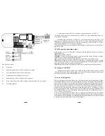
Connection diagram of the elements of the regulator is presented on fig. 3
THE REGULATOR IS SUPPLIED BY 230V/50HZ .
ANY MOVES REGARDING INSTALLATION SHOULD BE MADE AT
THE DISCONNECTED MAINS.
THE REGULATOR HAS TO BE CONNECTED TO THE MAINS WITH THE
ZERO-PIN.
(CHOOSE)
(ON/OFF)
(CONFIRM)


