background image

25

I25

I24

I23

I22

I21

I20

I19

I18

I17

I16

I15

tr

sv

p

t

p

l

n

o

n

l

it

fr

fi

es

en

d

e

cz

cn

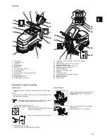
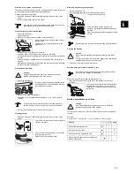
Overview

1

Dosing cup

2

Filling level (max.)

3

Dirt sieve

4

Recovery tank

5

Recessed grip

6

Brush unit

7

Tools (brush, pad drive, etc.)

8

Solution tank filter

9

Drain opening

10

Emptying hose for solution tank (blue cap)

11

Solution tank

12

Hour counter (optional)

13

Machine handle

14

Operating lever (brush drive)

15

Adjusting lever for the inclination of the machine handle

16

Suction filter

17

Float (overfilling protection for recovery tank)

18

Suction hose (turbine - cap)

19

Cable support for charging unit power cord

20

Manual solution flow adjustment

21

Foot pedal squeegee

22

Suction hose (squeegee - cap)

23

Squeegee

24

Foot lever for the tool

25

Emptying hose for recovery tank (red cap)

26

Main (ON/OFF) switch

27

Suction unit switch

28

Solution switch

Preparation for operation/Operation

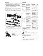
Attaching tools

Check: 
• that the brush has not fallen below the red mark or a brush length of 1 cm.
• the pad for wear before using.

Attach squeegee

1
2

3

4

5

6

7

8

9

10

11

12

13

14

max.60

°

C

max.140

°

F

15

16

17

18

19

21

22 23

24

25

26

27

28

20

• Switch the machine off and pull the power supply cord out of the mains 

socket.

Working with worn out, damaged and or wrong tools, could result 
in possible damage to floors or their protective layers.

• Position the tool below the brush unit.
• Plug the power supply cord into the mains socket.

• Switch the machine on (main (ON/OFF) switch).

The main switch lights up.

• Unlatch the foot lever and slowly lower the tool.

• Briefly pull the brush drive bar.

By doing this the tool will be centered and coupled.

• Switch the machine off.

• Lay the squeegee under the squeegee holder 

so that the nozzle holder is underneath the 
connection flap.

• Press the foot lever down until the squeegee 

locks into place.

• Attach the suction hose to the squeegee.

Summary of Contents for swingo 455E

Page 1: ...swingo 455E V003 12089 85 1223 I25 I24 I23 I22 I21 I20 I19 I18 I17 I16 I15 tr sv pt pl no nl it fr fi es en de cz cn 12089 85 ...

Page 2: ...ly inflammable materials such as petrol solvents fuel oil dusts etc are stored or processed The electrical or mechanical components could lead to the ignition of these materials This machine must not be used in rooms that are subject to electro magnetic loading electro smog STOP t STOP STOP STOP Do not use this machine to vacuum toxic poisonous caustic or irritating substances e g hazardous dusts ...

Page 3: ...EN 62233 EN 55014 1 EN 55014 2 EN 61000 3 2 EN 61000 3 3 It is ensured through internal measures that series production units conform at all times to the requirements of current EU Directives and relevant standards Download Link for the original EU Declaration of Conformity http www espares diversey com manuals Caution This machine should only be operated with a positive ground earth connection On...

Page 4: ...ch 28 Solution switch Preparation for operation Operation Attaching tools Check that the brush has not fallen below the red mark or a brush length of 1 cm the pad for wear before using Attach squeegee 1 2 3 4 5 6 7 8 9 10 11 12 13 14 max 60 C max 140 F 15 16 17 18 19 21 22 23 24 25 26 27 28 20 Switch the machine off and pull the power supply cord out of the mains socket Working with worn out damag...

Page 5: ...clothing while working with this machine Lower the squeegee Unlatch the foot lever and slowly lower the tool Plug the power supply cord into the mains socket Switch the machine on main ON OFF switch The main switch lights up Push the cleaning solution switch The main switch lights up Push the suction unit switch The indicators light up briefly Adjust the volume of the cleaning solution max 60 C ma...

Page 6: ...ge to the floor coating Switch the machine off Once the solution tank has been drained screw the yellow cap from the solution tank filter and pull it away from its holder Rinse the filter under running water If necessary the filter should be descaled with a 10 TASKI calcacid solution The filter is lower than the tank outflow A residual amount of solution will flow out once the filter cap has been ...

Page 7: ... and screw the star grip in place again Switch the machine off and pull the power supply cord out of the mains socket The yellow suction filter can be easily removed quick fit seal Clean it under running water using a brush let it dry out well Brush the yellow suction filter with a soft brush or remove the fluff with a cloth 3 1 2 Malfunction Possible causes Troubleshooting page Machine does not r...

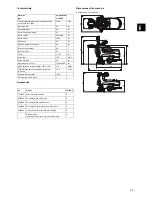
Page 8: ...kg Solution tank nominal 22 l Recovery tank 25 l Tools 1 x 43 cm Brush rpm 160 min 1 Brush pressure 25 kg Dimensions L x W x H 139x69x110 cm Noise emission level according to ISO 11201 70 dB A Total vibration value of hand arm vibration to ISO 5349 0 5 m s2 Splash water protection IPX4 Electrical protection class I Nr Article CO455 0 7510829 Pad drive Instalok 43cm X 8504750 Scrubbing brush 43cm n...

Reviews: