©Copyright Task Force Tips, Inc. 1999 - 2011
LIM-030 April 29, 2011 Rev13
19
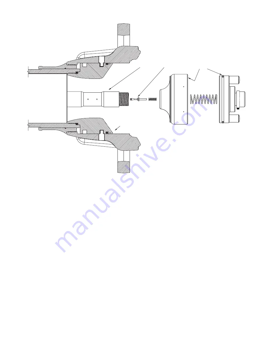
RETURNSPRING
CYLINDER
SHAFT
POPPET
CONTROL
SPRING
LUBE
PISTON
FIG 5D - Masterstream 4000 Nozzle Front End Parts
Page 1: ...operation servicing and safety procedures associated with the Masterstream Series firefighting nozzles This manual should be kept available to all operating and maintenance personnel MASTERSTREAM 1000 150 1000 GPM 100 PSI 600 4000 LPM 7 BAR 700 KPA MASTERSTREAM 1250S 150 1250 GPM 100 PSI 600 4500 LPM 7 BAR 700 KPA MASTERSTREAM 1250 300 1250 GPM 70 120 PSI 1100 4700 LPM 4 8 8 3 BAR 480 830 KPA MAST...
Page 2: ...level required to operate any equipment you may be called upon to use 5 It is your responsibility to know that your equipment is in operable condition and has been maintained in accordance with the manufacturer s instructions 6 Failure to follow these guidelines may result in death burns or other severe injury FEMSA Fire and Emergency Manufacturers and Service Association P O Box 147 Lynnfield MA ...
Page 3: ...es are constructed of hardcoat anodized aluminum and UV resistant rubber Their rugged construction is compatible with the use of fresh water as well as firefighting foam solutions A summary of each nozzle s characteristics is shown in the table below AUTOMATIC SERIES FLOW RANGE NOMINAL PRESSURE STANDARD COUPLING GPM L min PSI BAR KPA 100 MASTERSTREAM 1000 150 1000 600 4000 100 7 2 5 NH FEMALE MAST...
Page 4: ...ow conductivity refined products Applying foam over a low conductivity liquid of sufficient depth to retain the charge created as the foam blanket drains Streaming currents as water or foam is introduced into the storage tank 1 WARNING Water is a conductor of electricity Application of water solutions on high voltage equipment can cause injury or death by electrocution The amount of current that m...
Page 5: ...in figures 1A 1F See catalog for model numbers and details Coupling Halo Ring Stream Shaper Bumper Coupling Halo Ring Stream Shaper Bumper Fig 1A Stream Shaper moved manually by rotating Halo Ring Automatic Version Fig 1B Stream Shaper moved manually by rotating Halo Ring Manual Version Serial Number Hydraulic Ports Fig 1C Stream Shaper moved manually by rotating Bumper Fig 1D Stream Shaper moved ...
Page 6: ...he stream shaper counterclockwise will result in an increasingly wider pattern For linearly actuating models pushing the stream shaper forward as seen from the operating position behind the nozzle will result in a straight stream pattern Moving the shaper back will result in an increasingly wider pattern Since the stream trim point varies with flow the nozzle should be trimmed after changing the f...
Page 7: ...OZZLE OPERATION Automatic nozzles operate by sensing the pressure at the nozzle s inlet and adjusting the discharge opening to maintain a constant pressure throughout the flow range of the nozzle For example when the pressure at the inlet increases the exit area is automatically increased until the inlet pressure returns to the nominal pressure of the nozzle Note Inlet pressure of a Masterstream S...
Page 8: ... 0 2 4 6 8 10 0 1000 2000 3000 4000 5000 6000 7000 FLOW L MIN PRESSURE BAR KPA 100 FLOW RANGE FIG 3A Masterstream 1000 Pressure Performance 0 0 20 2 40 4 60 6 80 8 100 10 120 140 160 0 0 200 2000 400 4000 600 6000 800 1000 1200 1400 1600 FLOW GPM FLOW L MIN OPERATING ENVELOPE PER NFPA 1964 PRESSURE PSI PRESSURE BAR KPA 100 MASTERSTREAM 1250s PERFORMANCE FIG 3B Masterstream 1250s Pressure Performan...
Page 9: ...160 0 200 400 600 800 1000 1200 1400 1600 1800 2000 FLOW GPM PRESSURE PSI 0 2 4 6 8 10 0 1000 2000 3000 4000 5000 6000 7000 FLOW L MIN PRESSURE BAR KPA 100 FLOW RANGE 110 PSI SETTING 100 PSI SETTING 90 PSI SETTING 80 PSI SETTING 70 PSI SETTING 120 PSI SETTING 8 BAR 7 BAR 6 BAR 5 BAR FIG 3C Masterstream 1250 Pressure Performance To adjust the Master 1250 and 1500 simply twist the pressure adjustmen...
Page 10: ...Pressure Performance TO ADJUST PRESSURE SETTING 1 LOOSEN BOTH SCREWS 2 ADJUST PRESSURE KNOB 3 LOCK KNOB BY TIGHTENING BOTH SCREWS UNTIL SNUG NOTE LOCKED KNOB SHOULD NOT ROTATE BY HAND POINTER INDICATES OPERATING PRESSURE IMPORTANT DO NOT LOOSEN THIS SCREW MASTERSTREAM 4000 PERFORMANCE 0 20 40 60 80 100 120 140 160 0 1000 2000 3000 4000 5000 6000 FLOW GPM PRESSURE PSI 0 2 4 6 8 10 0 4000 8000 12000...
Page 11: ...PSI Fig 3 2 Nozzle Flow Characteristics 3 3 FLOW CHARACTERISTICS OF MASTERSTREAM 1000 FIXED NOZZLE The Masterstream 1000 Fixed Flow Nozzle is set to the desired flow by adjusting the baffle and locking it in place with a jam nut The nozzle is adjusted and flow tested at the factory at time of order If the baffle is moved for example to flush the nozzle then the baffle must be readjusted to obtain ...
Page 12: ...om step 2 and the following equation the flow with an automatic nozzle can be calculated for your particular installation Where Qauto automatic nozzle flow in GPM or LPM Pauto nominal nozzle operating pressure in PSI or BAR Q P P C auto in line auto Mount a graph or table of the results adjacent to the in line pressure gauge Deliver any desired flow by adjustment of pump pressure 3 5 STREAM TRAJEC...
Page 13: ...ORIZONTAL DISTANCE FEET VERTICAL DISTANCE FEET 0 5 10 15 20 0 10 20 30 40 50 60 70 80 90 METERS METERS MASTERSTREAM 1250 100 PSI 7 BAR 700 KPA A B C D E GPM LBS CURVE FLOW REACTION A 300 150 B 500 250 C 800 400 D 1000 510 E 1250 630 LPM KGF CURVE FLOW REACTION A 1100 70 B 1900 120 C 3000 180 D 3800 230 E 4700 290 0 10 20 30 40 50 60 70 80 0 20 40 60 80 100 120 140 160 180 200 220 240 260 280 300 H...
Page 14: ...RIZONTAL DISTANCE FEET VERTICAL DISTANCE FEET 0 5 10 15 20 0 10 20 30 40 50 60 70 80 90 METERS METERS MASTERSTREAM 1500 100 PSI 7 BAR 700 KPA A B C D E GPM LBS LPM KGF CURVE FLOW REACTION CURVE FLOW REACTION A 300 150 A 1100 70 B 600 300 B 2300 140 C 1000 510 C 3800 230 D 1250 630 D 4700 290 E 1500 760 E 5700 350 0 10 20 30 40 50 60 70 80 0 20 40 60 80 100 120 140 160 180 200 220 240 260 280 300 H...
Page 15: ...IZONTAL DISTANCE FEET VERTICAL DISTANCE FEET 0 5 10 15 20 0 10 20 30 40 50 60 70 80 90 METERS METERS MASTERSTREAM 2000 100 PSI 7 BAR 700 KPA A B C D E GPM LBS LPM KGF CURVE FLOW REACTION CURVE FLOW REACTION A 300 150 A 1100 70 B 600 300 B 2300 140 C 1000 510 C 3800 230 D 1500 760 D 5700 350 E 2000 1010 E 7500 460 0 10 20 30 40 50 60 70 80 0 20 40 60 80 100 120 140 160 180 200 220 240 260 280 300 H...
Page 16: ...600 2100 CURVE A B C D E LPM FLOW 2300 3800 7600 11000 15000 KGF REACTION 150 240 500 730 950 VERTICAL DISTANCE FEET 0 10 20 30 METERS 0 20 40 80 METERS 60 100 120 0 20 40 60 80 100 0 40 80 120 160 200 240 280 320 360 400 HORIZONTAL DISTANCE FEET A B C D E MASTERSTREAM 4000 100 PSI 7 BAR 700 KPA CURVE A B C D E GPM FLOW 600 1000 2000 3000 4000 LBS REACTION 350 580 1200 1700 2300 CURVE A B C D E LP...
Page 17: ...pring force The spring must be compressed to reinstall A long white push rod is part of the cylinder assembly Pull cylinder straight out until push rod clears shaft Notes for 1250 1500 2000 and 4000 Nozzles Remove the piston return spring and cylinder Remove the small spring and stainless steel poppet from the center of the shaft as a unit 4 Remove flush debris 5 Reassemble the nozzle if necessary...
Page 18: ... Rev13 18 CONTROL SPRING SHAFT POPPET CYLINDER RETURN SPRING LUBE LUBE LUBE LUBE PISTON FIG 5B Masterstream 1250 and 1500 Front End Parts RETURN SPRING CYLINDER SHAFT POPPET CONTROL SPRING LUBE LUBE LUBE LUBE PISTON FIG 5C Masterstream 2000 Nozzle Front End Parts ...
Page 19: ... Copyright Task Force Tips Inc 1999 2011 LIM 030 April 29 2011 Rev13 19 RETURN SPRING CYLINDER SHAFT POPPET CONTROL SPRING LUBE LUBE LUBE LUBE PISTON FIG 5D Masterstream 4000 Nozzle Front End Parts ...
Page 20: ...ect TFT will examine the equipment If TFT determines that there is a defect attributable to it TFT will correct the problem within a reasonable time If the equipment is covered by this limited warranty TFT will assume the expenses of repair If any defect attributable to TFT under this limited warranty cannot be reasonably cured by repair or replacement TFT may elect to refund the purchase price of...