©Copyright Task Force Tips, LLC 2002 - 2018
LIA-200 March 20, 2018 Rev19
8
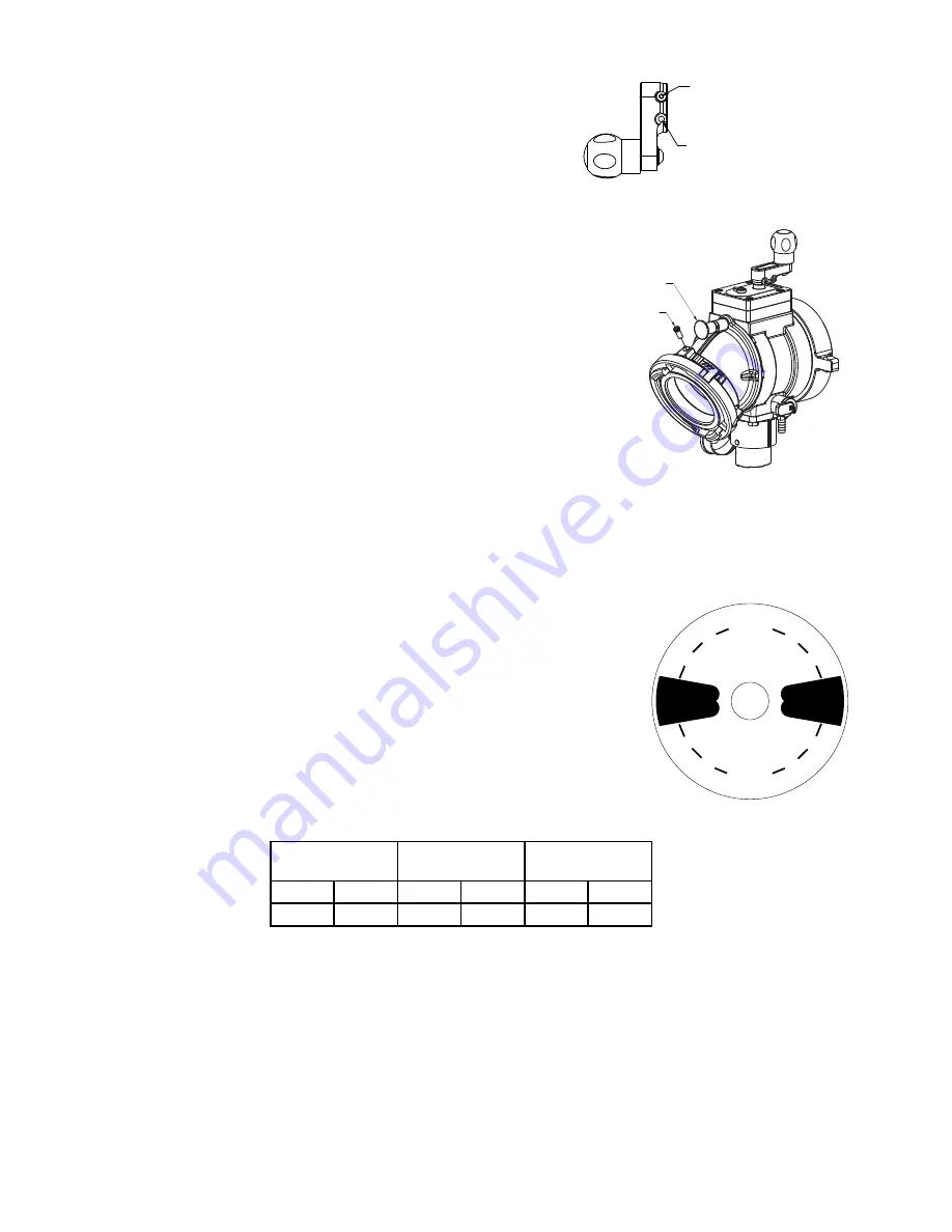
4.8 CHANGING OFFSET OF CRANK HANDLE
When equipped with a crank handle, two offset positions are available to adjust
the swing radius of the crank and knob as shown. The longer offset position
offers reduced effort to operate the valve. The shorter offset is available to avoid
interference with other equipment on the apparatus. To change the offset, remove
two 1/4”-20 x 1/2” button head cap screws from crank. Place crank in desired
position and replace screws. Apply Blue Loc-Tite thread locking compound to all
of the screw threads.
LONGER OFFSET POSITION
2.6" [67mm]
SWING RADIUS
SHORTER OFFSET POSITION
1.6" [41mm]
SWING RADIUS
4.9 CHANGING COUPLING LOCK-OUT
To change a coupling from rigid to full time swivel, use a 7/32” Allen driver to
back out the lockout screw until the coupling moves freely.
To change a coupling from full time swivel to rigid, first align the pull pin in the
elbow to vertical. Rotate the coupling until the lockout screw is aligned with the
pull pin. Use a 7/32” Allen driver to tighten the lockout screw into the lockout
divot in the elbow. Do not tighten the screw onto the polymer bearing strip.
PULL PIN
LOCK-OUT SCREW
4.10 STORZ ‘SUCTION GASKET’ REQUEST
If your application of this product requires drafting, you may need a suction
gasket, please call 1-800-348-2686 to receive a free suction gasket by mail.
Part Numbers: 4” STORZ - item # A4216, 5” STORZ - item # A4221, 6” Storz
- item # A4273
5.0 USE
5.1 INTAKE ELBOW
The intake elbow swivels 360 degrees to help prevent hose kinks, and make connection of suction lines easier. The intake can be
turned forward or backward to help make connections in tight places if the water supply is in front of or behind the truck. To turn the
elbow, pull the shot pin knob on top of the elbow. The elbow will lock into a detent every 45 degrees. There is a hole on the side of
the elbow that can be used to attach the lanyard or chain of a cap by use of a key ring . The elbow may be swivelled to any of eight
positions by pulling the shot pin knob.
5.2 VALVE OPERATION
CLOSED
OPEN
OPEN
3
4
1
2
1 4
1
4
1
2
3
4
CLOSED
3
4
3
4
1
2
1
2
1
4
1
4
The valves covered by this manual utilize positive stops at the OPEN and CLOSED positions.
Attempting to close a valve further than the positive stops will not result in a tighter seal
between the ball and valve seat. All valves include markings to indicate the direction of handle
rotation to open the valve.
Valves with hand cranks include a valve position indicator. To open the valve, turn the hand
crank until the valve position indicator shows OPEN. To close the valve, turn the hand crank
the opposite way until the valve position indicator shows CLOSED.
Up to the maximum rated pressure, operating torque should never exceed the values in the
table below. If greater torque is required to operate the valve, then that is an indication that
the valve needs maintenance. Exceeding 30 ft-lb / 41 N-m torque may damage the appliance.
Kicking or standing on the valve controls is considered misuse of the appliance.
Valve Seat Bore
Size
Max Acceptable
Torque
Max. Acceptable
Force on Knob
3.65 in
93 mm
12 ft-lb
16 N-m
55 lb
25 kg
5.25 in 133 mm
30 ft-lb
41 N-m
137 lb
62 kg
For valves with parallel shaft gearboxes, exceeding 30 ft-lb will result in permanent damage to several components in the gearbox.
The damage may not be outwardly obvious, but could result in inability to operate the valve. To restore normal operation, the entire
gearbox must be replaced after relieving pressure from the valve.
For valves with worm drive gearboxes, exceeding 45 ft-lb will cause one side of the crank shaft to shear off. This is intentional to
prevent further damage to the gearbox. If the shaft shears off, the valve can be operated temporarily using a wrench on the ½” hex
on the opposite side of the crankshaft. For repair instructions, see section 9.2 CRANKSHAFT OVERRIDE AND REPLACEMENT.


