background image

2 – Using the card : BASS MANAGEMENT option

  TASCAM IF-SM/DM Owner’s Manual 

13

BASS MANAGEMENT option

The 

BASS MANAGEMENT

 screen allows the 

selection of one of two bass management 
techniques, Type 1 and Type 2.

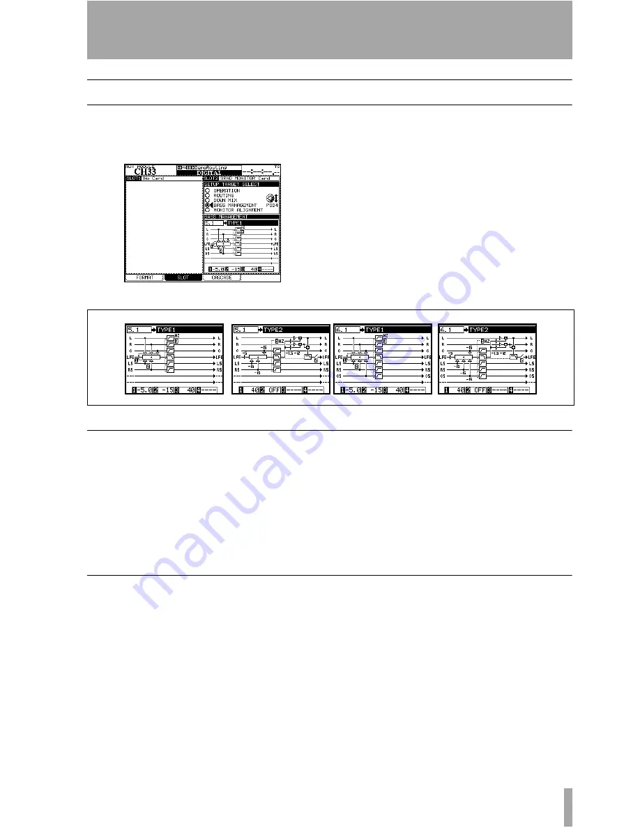
Figure 2.19: BASS MANAGMENT option  screen

These are illustrated graphically below as they 
are implemented in 5.1 surround mode.

Figure 2.20: Type 1 and Type 2 bass management for 5.1 and 6.1 settings

Type 1 bass management

There are three parameters:

The amount of attenuation supplied to the 

LFE channel before bass management occurs, 
either –5dB (default) or 10dB.

The amount of attenuation applied to the 

surround-LFE feed, either –15dB (default) or 
0dB.

The crossover frequency of the high-pass 

filters applied to all channels except the LFE, 
and the low-pass filter applied to the LFE. 
From 40Hz (default) to 130Hz in 10Hz steps.

Type 2 bass management

There are two parameters:

The crossover frequency of the high-pass 

filters and the low-pass filter in the system. 
From 40Hz (default) to 130Hz in 10Hz steps.

Turns the LFE 

ON

 or 

OFF 

(default).

Summary of Contents for IF-SM/DM

Page 1: ...This appliance has a serial number Please record the model number and serial number and retain them for your records Model number Serial number IF SM DM Surround Monitor Card OWNER S MANUAL D00885000A...

Page 2: ...SM DM analog outputs 4 Figure 2 1 The main surround monitor screen 5 Figure 2 2 The OPERATION option 5 Figure 2 3 SHIFTed number keys used for channel control 5 Figure 2 4 ROUTING option screen 7 Figu...

Page 3: ...slot into which you will fit the interface card Keep the retaining screws in a safe place If you are installing more than one card we suggest that you start from the top slot slot 1 and work downwards...

Page 4: ...or the IF FW card which must be fit ted in slot 1 any other interface card may be fitted in any expansion slot Connections The D sub 25 pin connector allows the connec tion of up to eight balanced ana...

Page 5: ...ls Switching downmix on and off Switching alternative speakers on and off Routing the internal oscillator on and off Turning bass management on and off Instant downmix to a 2 1 setting Setting the mon...

Page 6: ...speakers connected to the LC and RC channels which are not used in the surround patterns This allows the use of a pair of large stereo speakers together with smaller surround mon itors without the nee...

Page 7: ...Individual busses Pairs of busses Digital inputs 1 or 2 2 TR analog inputs The TDIF signals 1 through 3 The ADAT signal The signal of any card in a slot other than the surround monitor card In LRCS 5...

Page 8: ...they are folded into the target busses may be changed Figure 2 5 Example downmix screen showing attenuation points Attenuation In the on screen display the attenuation points are shown as inverted num...

Page 9: ...default underscored C L R 0 1 5 3 4 5 6 LS RS L R 0 3 6 CS LC L R 3 6 9 L R C LFE LS RS CS LC RC L R C LFE LS RS LC RC mute mute 3 3 4 5 6 L R C LFE LS RS CS LC RC L R C LFE LS RS LC RC mute mute mute...

Page 10: ...n Source Target Values in dB default underscored LFE C 3 6 9 LFE L R 3 6 9 LS LS summed and attenuated 3 RS RS Source Target Values in dB default underscored LFE C 3 6 9 LFE L R 3 6 9 LS S summed RS S...

Page 11: ...rear hard speaker configuration where the LS S signal is assigned to the CS speaker of a 6 1 configura tion not shown above LRCS stereo In the LRCS to stereo downmix the attenuation values are Table...

Page 12: ...wn mix there are no parameters changeable attenuation values The left and right signals are summed and attenuated by 3dB Figure 2 18 Stereo to mono downmix Source Target Values in dB default underscor...

Page 13: ...ment There are three parameters 1 The amount of attenuation supplied to the LFE channel before bass management occurs either 5dB default or 10dB 2 The amount of attenuation applied to the surround LFE...

Page 14: ...ctually driving one of the sur round channels you will have severe problems Use the ROUTING option on page 7 for this Use the mixer s oscillator set up to supply pink noise to allow you to set up and...

Page 15: ...essary so that it matches the first Trim levels can be adjusted 9 9dB in 0 1dB steps 6 Repeat this process until the levels of all channels as measured by the SPL meter are within a few dB of each oth...

Page 16: ...arlier to set the level to the desired reference level 4 Route the oscillator pink noise at nominal level through the surround system all channels 5 Adjust the amplification system so that the SPL met...

Page 17: ...E LS RS LC RC L R C LFE LS RS LC RC MUTE SOLO L R C LFE LS RS LC RC DAC ANALOG Output Select TRIM Surround Level LFE Level SPL Reference Moniotr Level dB dB dB dBc dBc Dimmer ALT SPK to 2 1 Level Sect...

Page 18: ...oscillator to MONITOR OUTPUT 1 8 Level max Signal delay 1 5 ms Fs 48 0kHz LINE to MONITOR OUTPUT 1 8 0 75 ms Fs 96 0kHz Mixer internal oscillator to MONITOR OUTPUT 1 8 X talk 90 dB 1kHz Mixer internal...

Page 19: ...o L4Z 1Z8 Canada TEAC MEXICO S A De C V Phone 52 555 581 5500 www tascam com Campesinos No 184 Colonia Granjes Esmeralda Delegaacion Iztapalapa CP 09810 Mexico DF TEAC UK LIMITED Phone 44 1923 438880...

Reviews: