3 – Automation Overview
TASCAM DM-24 Automation
15
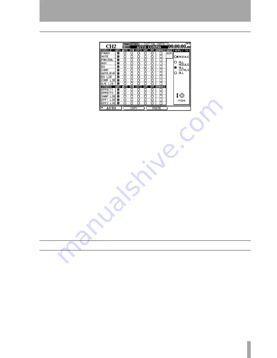
AUTO CONFIG
Figure 4 –
AUTO CONFIG display where automatic mode switching can be over-ridden.
The grid represented in the
AUTO CONFIG
display is
used to manually over-ride the automation’s mode
switching. The selected channel is displayed in the
upper left of the display. If the displayed channel is
part of a group, this is indicated in the upper right of
the grid.
The changes made in this grid are applied to channel
and controls selected by the
APPLY TO
buttons at the
right of the display. Use the rightmost POD to make
this selection. Note that it is not necessary to press
ENTER
to confirm this setting.
When a module or control is set to any mode except
Auto
using this display, that module or control
remains in that mode until it is reset back to
Auto
.
The settings made in this display are saved as part of
the mix data.
MODULE
When selected, the changes in this dis-
play will only be applied to the specified control on
the selected channel.
ALL MODULE
When selected, the changes in this
display are applied to a single control across all chan-
nels. For example, with
ALL MODULE
selected,
enabling
SAFE
in the
FADER
row places all mixer fad-
ers into Safe mode.
ALL CNTRLS
When selected, the changes in this
display are applied to all controls on the selected
channel. This applies the changes to the libraries.
ALL
When selected, the changes in this display are
applied to all controls on all channels.
COPY
This soft key copies the configuration of the
currently-selected channel into a special clipboard
where it can then be pasted to another channel.
PASTE
This soft key pastes the configuration copied
using the
COPY
soft key to the currently-selected
channel. Note that there is no Undo for this opera-
tion.
Channel LED Indicators
Each channel has an LED indicator immediately
above the fader. When automating a mix, these indi-
cators can be used to show whether a channel is writ-
ing, reading or reverting.
Use the
OPTION
display screen to set the function of
these indicators. The default use is as channel over-
load indicators, as explained in the main manual.
When used as automation indicators, they flash when
any control on a channel is writing or reverting. They
are lit steadily when all controls on a channel are
reading.
The global Revert LED above the
REVERT
key fol-
lows the behavior of the channel indicators when
they are used for automation.


