background image


1 - Introduction to the DA-45HR


  TASCAM DA-45HR 


7


Fingerprints on the tape may cause wear and damage 
to the tape deck heads.

DAT cassettes can only be loaded and unloaded 
when the tape deck is switched on. Do not leave cas-
settes in the deck when the deck is switched off.

Always store DAT cassettes in their plastic cases to 
prevent dust damage. Keep them away from mag-
netic fields (TV sets and monitors, speakers, etc.)

Although 180-minute DAT cassettes are available, 
we do not recommend their use, as the tape in these 
cassettes is thin, and may cause winding problems, 
and physical damage to the tape.

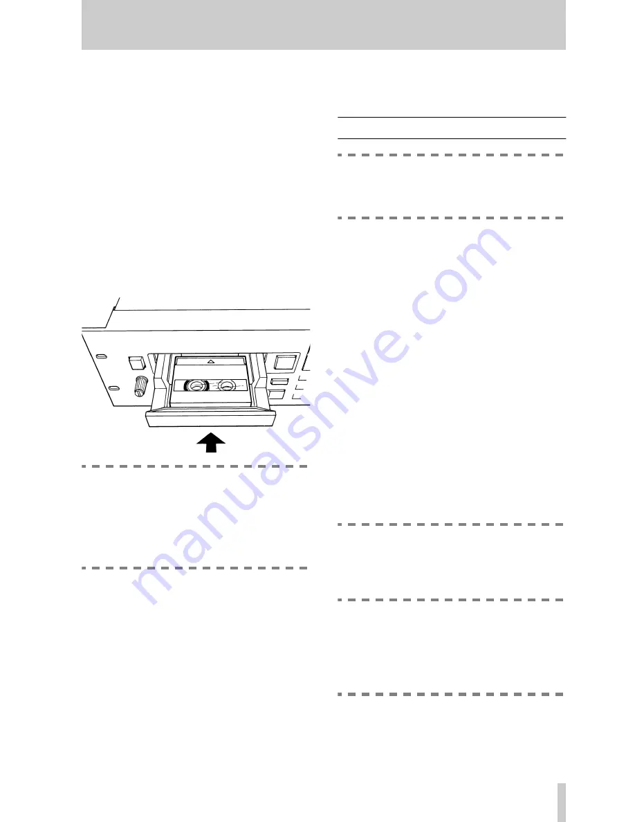
DAT cassettes play in one direction only. Always 
load DAT cassettes with the tape window uppermost, 
and the arrow on top of the cassette pointing into the 
tape deck, as illustrated below:


NOTE


Start recording on a new blank tape from the 
beginning of the tape. There is no need for a 
lead-in section, and recording from the start 
of the tape will record the subcode from the 
start, allowing accurate positioning within the 


tape.


Also note that DAT cassettes are fitted with a sliding 
write-protect tab to prevent accidental recording. The 
cassette is write-protected when the tab is closed.


1.4.1 Head cleaning


Never attempt to clean the head of a DAT deck in the 
same way that you clean the head of an analog tape 
deck. Always use a special DAT head cleaning cas-
sette. Follow the instructions on the cleaning cassette 
for optimum performance.

The head may need to be cleaned if you hear errors 
(noise) on playback or while recording. You can 
make a visual check of the error rates and error loca-

tions using the 


DISPLAY [24]


 key or the error dis-

play menu (3.19, "Viewing points at which block 
errors have occurred").


1.5 Making connections


NOTE


Before making any audio or word clock con-
nections to the tape deck, make sure that all 


equipment is turned off.


1.5.1 Making analog connections


Use balanced cables to make connections between 
the 


BALANCED  INPUT


 (female) and 


OUTPUT


(male) XLR connectors of the tape deck, and the out-
puts and inputs of other audio equipment operating at 
the profes4 dBu level. The wiring standards 
for the XLR connections are printed on the rear panel 
of the tape deck (1 = ground, 2 = hot, 3 = cold)

Use unbalanced cables to make connections between 
the unbalanced input and output RCA connectors of 
the tape deck and the outputs and inputs of audio 
equipment operating at other levels.


1.5.2 Making digital audio connections


Use cables wired in accordance with the AES/EBU 
standard to connect the 


DIGITAL (AES/EBU) 

INPUT


 (male) and 


OUTPUT


 (female) XLR connec-

tors of the tape deck to other digital audio equipment.

Use unbalanced cables to connect the 


DIGITAL 

(COAXIAL) INPUT


 and 


OUTPUT


 RCA connec-

tors of the tape deck to other digital audio equipment.


NOTE


The use of analog cables is not recom-
mended for digital audio use, and TASCAM 
cannot guarantee reliable performance if such 


cables are used for digital audio connections.


1.5.3 Making word synchronization 

connections


Use standard BNC-terminated cables to connect the 
word in connector of the tape deck to the word clock 
output of other device. 


NOTE


There is no dedicated word output. Since both 
the AES/EBU and SPDIF formats contain a 
clock signal, if the tape deck is to be used as 

Summary of Contents for DA-45HR

Page 1: ...erature accompanying the appliance The lightning flash with arrowhead symbol within an equilateral triangle is intended to alert the user to the presence of uninsulated dangerous voltage within the pr...

Page 2: ...pe should be used and be sure to re fit the fuse cover IF IN DOUBT CONSULT A COMPETENT ELECTRICIAN TO THE USER This equipment has been tested and found to comply with the limits for a Class A digital...

Page 3: ...g structure grounding of the lead in wire to an antenna discharge unit size of grounding conductors location of antenna discharge unit con nection to grounding electrodes and requirements for the grou...

Page 4: ...Y 16 32 SHIFT 16 2 5 Rear panel 16 33 DIGITAL AES EBU INPUT OUTPUT 16 34 DIGITAL COAXIAL 16 35 WORD IN and THRU AUTO TERM 16 36 CONTROL I O 16 37 REMOTE IN 17 38 IN 17 39 BALANCED ANALOG inputs 17 40...

Page 5: ...ursor keys 28 55 COUNTER MODE 28 56 MARGIN RESET 28 57 CHAR 28 58 DISPLAY 28 59 SKIP PLAY 28 60 SINGLE PLAY 28 61 REPEAT 28 5 1 Remote control transport keys 28 62 SKIP keys 28 63 MEMO 1 and MEMO 2 ke...

Page 6: ...ust be transported later In addition to the tape deck itself the carton should contain a rack mount screw kit and a detachable 2 m 6 ft power cord If any items are missing or appear to have been dam a...

Page 7: ...ing You can make a visual check of the error rates and error loca tions using the DISPLAY 24 key or the error dis play menu 3 19 Viewing points at which block errors have occurred 1 5 Making connectio...

Page 8: ...d to the REMOTE IN jack using the 5 m approximately 16 ft cable of the RC D45 WARNING Do not attempt to use the tape deck with any remote control unit except one designed especially for use with this...

Page 9: ...TASCAM DA 45HR 9...

Page 10: ...described more fully below COUNTER MODE 21 and DISPLAY 24 Above the tape counter in the display are two bar graph peak level meters which show either the level of the input signals or the level of th...

Page 11: ...is necessary to select the bit resolution for playback the tape deck recognizes the recording mode in which the tape was recorded and adjusts accordingly When the tape deck is in record ready mode as...

Page 12: ...forwards or backwards by the appropriate number of programs pressing the skip forward key once will move the tape to the beginning of the next program etc While the tape is locating the display will...

Page 13: ...connections etc are properly made before recording starts If all clock connections are in order the display will show ANALOG in AES EBU or COAXIAL The peak level meters will show the signal levels rec...

Page 14: ...turning the DATA dial to locate to the start of the program and start playing Press the PAUSE key within five seconds of turning the DATA dial to locate to the start of the program and put the tape d...

Page 15: ...active If titles have been recorded on the tape see 4 8 Character editing titling CHAR is shown on the display and the characters comprising the title are shown on the display here the word TAS CAM i...

Page 16: ...ither AES EBU or SPDIF format as selected in 3 6 Dig ital output format The format of data received AES EBU or SPDIF is automatically detected 34 DIGITAL COAXIAL These RCA connectors provide digital a...

Page 17: ...2 hot 3 cold The nom inal impedance of these connectors is greater than 25 k 40 UNBALANCED ANALOG inputs These RCA connectors provide unbalanced inputs at a nominal 10 dBV level The nominal impedance...

Page 18: ...48dB 54dB 57dB and 60dB The default value is 48dB 3 3 Auto ID time When the AUTO ID function is enabled AUTO ID 26 signals which exceed the level set in 3 2 Auto ID level will automatically start the...

Page 19: ...sing dither different circum stances demand different settings The default setting here is off 3 9 Copy prohibit Sets the level of copy protection for tapes recorded using this tape deck The menu item...

Page 20: ...DATA dial 20 The values available are 0 1 2 3 4 and 5 seconds The default value is 0 seconds 3 14End tally signal Controls the timing of the tape end tally signal trans mitted through the CONTROL I O...

Page 21: ...hat the display shows 3 19Viewing points at which block errors have occurred This display is shown if the MENU key is pressed once more following the reset screen above This displays up to five points...

Page 22: ...titles It allows the checking of titles which are longer than the display allows and scrolls them across the display See Character editing titling on page 26 4 3 INS and DEL These keys may be used in...

Page 23: ...port controls except STOP are disabled NOTE If there is no cassette inserted or if the cas sette is write protected the message Rec Protect will appear in the display when the ID SELECT key is pressed...

Page 24: ...SK as appropriate is shown in the display When the ID has been located the START ERASE or SKIP ERASE shown in the display will start flashing and the RECORD and PLAY indicators will light After the I...

Page 25: ...is should be remembered when setting program numbers 4 5 The EDIT key The EDIT key SHIFTed MENU 28 allows the following operations to the performed Editing of the first memory location Editing of the...

Page 26: ...LAY key is pressed the first program step will be played and the tape will locate to the start of the next program step and enter pause mode until the PLAY key is pressed again The pro cess continues...

Page 27: ...s soon as the first title is read from tape Use the CHAR key to display the last title which has been read from tape While the title is displayed all other tape counter numerals are replaced by the ch...

Page 28: ...will be located to the start of the program and the deck will enter pause mode When editing and entering titles these keys may be used as a convenient way of entering characters Repeated presses of a...

Page 29: ...key 18 on the main unit 68 STOP Equivalent to the STOP key 14 on the main unit 69 PLAY Equivalent to the PLAY key 15 on the main unit 70 PAUSE Equivalent to the PAUSE key 16 on the main unit 71 RECORD...

Page 30: ...ts balanced XLR 3 31 type Nominal input level 4dBu FS 16 18 20 dBu Maximum input level 20 22 24 dBu Nominal impedance 10 k Analog inputs unbal anced RCA Nominal input level 10dBV Maximum input level 6...

Page 31: ...vel and press the RECORD key again RecProtect The cassette s sliding write pro tect tab is in the write protect position TapeMode HR TapeMode NOR An attempt is being made to record on a tape which has...

Page 32: ...oxley Centre Watford Herts WD1 8YA U K TEAC DEUTSCHLAND GmbH Phone 0611 71580 Bahnstrasse 12 65205 Wiesbaden Erbenheim Germany TEAC FRANCE S A Phone 01 42 37 01 02 17 Rue Alexis de Tocqueville CE 005...

Reviews: