


8
TARGET ECO I FEEDING, rev.09
TARGET ECO I FEEDING
2.3.2
Feed Distribution Process
The feed delivery process starts at the
beginning of a feed cycle. At that moment,
the controller sends the first feed ration
to the proper drop(s). It then waits for the
drops to empty out (rest time) before clean-
ing out the feed line. When the cleaning
process is over, the controller starts deliv-
ering the following ration (if applicable).
1)
Step 1 – Feed Delivery
•
Opening of the Drops:
With an actuator:
At the start-up of a feed cycle, the con-
troller opens the actuator to the position
associated with the first ration.
Without an actuator
:
At the start-up of a feed cycle, the con-
troller opens all drops that are asking for
the first feed ration.
•
Feed Distribution:
With a proximity sensor to stop the feeder:
The feeder runs while drops are opened. It
keeps on running up until the drops are full.
(The controller knows the drops are full
when the proximity sensor associated with
the ration detects feed. If only one prox-
imity sensor is used, the controller consid-
ers drops to be full when this sensor de-
tects feed).
Note that if a proximity sensor is used, an
alarm is generated if the sensor does not
detect feed after the
“Max Run Time”
. This
type of alarm generally occurs when a bin
is empty.
Without a proximity sensor:
Once the drops are opened, the feeder runs
during the
“Max Run Time”
associated with
the ration and then stops.
FEED CYCLE
STEP 1
STEP 2
STEP 3
STEP 1
STEP 2
STEP 3
Feed
Rest
Clean
Feed
Rest
Clean
Ration #X
Ration #X +1
2)
Step 2 – Resting Time
When drops are full, the controller stops
the feeder during the
“Rest Delay”.
This
delay represents the period of time re-
quired to empty out the drops.
3)
Step 3 – Cleanout
Cleanout periods allow evacuating feed left-
overs from the feed line. To empty the feed
line, the controller restarts the feeder while
the drops are opened. An optional cleanout
auger can also be used to send feed left-
overs back to their original bin.
During the cleanout period, the feeder
motor and the optional cleanout auger are
activated in order to evacuate feed from
the line. This cleaning period can either end
after a user-defined delay or when a cer-
tain proximity sensor stops detecting feed
(enable the “Feed Gap Delay” in the In-
stallation Setup if you want to use a prox-
imity sensor to stop the cleaning period
(see sec. 5.3)).
The controller repeats step 1 to
3 for each ration to be delivered
during the cycle.
37
TARGET ECO I FEEDING, rev.09
TARGET ECO I FEEDING
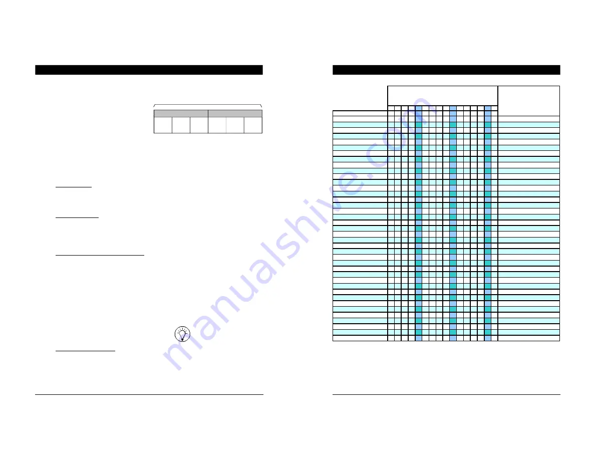
ID NUMBER
of the relay panel
(ID # 2 to ID #19)
17 18 19 20 21 22 23 24 25 26 27 28 29 30 31 32
OUTPUTS
1
2
3
4
5
6
7
8
9 10 11 12 13 14 15 16
Drop 19
_________ ( ID #2 to ID #19)
Drop 20
_________ ( ID #2 to ID #19)
Drop 21
_________ ( ID #2 to ID #19)
Drop 22
_________ ( ID #2 to ID #19)
Drop 23
_________ ( ID #2 to ID #19)
Drop 24
_________ ( ID #2 to ID #19)
Drop 25
_________ ( ID #2 to ID #19)
Drop 26
_________ ( ID #2 to ID #19)
Drop 27
_________ ( ID #2 to ID #19)
Drop 28
_________ ( ID #2 to ID #19)
Drop 29
_________ ( ID #2 to ID #19)
Drop 30
_________ ( ID #2 to ID #19)
Drop 31
_________ ( ID #2 to ID #19)
Drop 32
_________ ( ID #2 to ID #19)
Drop 33
_________ ( ID #2 to ID #19)
Drop 34
_________ ( ID #2 to ID #19)
Drop 35
_________ ( ID #2 to ID #19)
Drop 36
_________ ( ID #2 to ID #19)
Drop 37
_________ ( ID #2 to ID #19)
Drop 38
_________ ( ID #2 to ID #19)
Drop 39
_________ ( ID #2 to ID #19)
Drop 40
_________ ( ID #2 to ID #19)
Drop 41
_________ ( ID #2 to ID #19)
Drop 42
_________ ( ID #2 to ID #19)
Drop 43
_________ ( ID #2 to ID #19)
Drop 44
_________ ( ID #2 to ID #19)
Drop 45
_________ ( ID #2 to ID #19)
Drop 46
_________ ( ID #2 to ID #19)
Drop 47
_________ ( ID #2 to ID #19)
Drop 48
_________ ( ID #2 to ID #19)
Drop 49
_________ ( ID #2 to ID #19)
Drop 50
_________ ( ID #2 to ID #19)
Drop 51
_________ ( ID #2 to ID #19)
Drop 52
_________ ( ID #2 to ID #19)
Drop 53
_________ ( ID #2 to ID #19)
Drop 54
_________ ( ID #2 to ID #19)
Drop 55
_________ ( ID #2 to ID #19)
Drop 56
_________ ( ID #2 to ID #19)
Drop 57
_________ ( ID #2 to ID #19)
RELAY NUMBER
Relay 1-16 & Relay 17-32 = second 16-relay strip of 32
outputs relay panel