REV. 11
M 890-00035 rev. 09
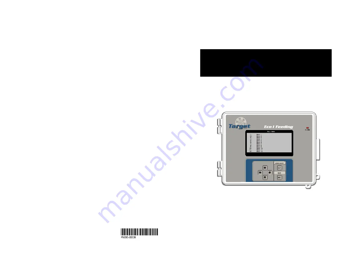
TARGET
ECO I FEEDING
Feed Distribution System for Hogs
USER’S MANUAL
Page 1: ...REV 11 M 890 00035 rev 09 TARGET ECO I FEEDING Feed Distribution System for Hogs USER S MANUAL...
Page 2: ...09 TARGET ECO I FEEDING NOTICE Every effort has been made to ensure that this manual is complete accurate and up to date The information contained in it is however subject to change without notice du...
Page 3: ...see Clock output Toggle switch 10 Transfer Configuration transfer 34 U USB Drive 34 User password 16 V Valves see Cleanout valve or Fill augers Version software 23 W Weighing error 31 Window size Sett...
Page 4: ...sor Conditions current 30 Configuration module 34 Connections 12 Consumption see Feed consumption Contrast LCD screen 13 34 Controller Backup see Memory card Features 6 Installation setup 17 19 Locati...
Page 5: ...circuit The room temperature where the controller is located must always remain between 32 F and 104 F 0 C to 40 C For Indoor use only To avoid exposing the controller to harmful gases or excessive hu...
Page 6: ...type of ration that is distributed to the animals over time It is thus pos sible to increase the number of feed cycles or to switch rations as the animals grow up Cleanout Cleanout periods allow evacu...
Page 7: ...p 85 _________ ID 2 to ID 19 Drop 86 _________ ID 2 to ID 19 Drop 87 _________ ID 2 to ID 19 Drop 88 _________ ID 2 to ID 19 Drop 89 _________ ID 2 to ID 19 Drop 90 _________ ID 2 to ID 19 Drop 91 ___...
Page 8: ...anout auger can also be used to send feed left overs back to their original bin During the cleanout period the feeder motor and the optional cleanout auger are activated in order to evacuate feed from...
Page 9: ...D 2 to ID 19 Drop 3 _________ ID 2 to ID 19 Drop 4 _________ ID 2 to ID 19 Drop 5 _________ ID 2 to ID 19 Drop 6 _________ ID 2 to ID 19 Drop 7 _________ ID 2 to ID 19 Drop 8 _________ ID 2 to ID 19 D...
Page 10: ...ontrolled by an actuator Cleanout Auger optional Cleanout valves for rations 1 8 if a cleanout auger is used Cleanout Master Valve if a cleanout au ger is used Air compressor if a cleanout auger is us...
Page 11: ...nt name CONTROLLER 2 DMP for instance This way the controller will never erase a file on the card 3 Update Firmware Choose 3 Update Firmware to download a new firmware file into your controller This p...
Page 12: ...pment and within easy reach of the operator It shall be marked as the disconnecting device for theequipment 3 2 2 Alarm Connection There are two types of alarms on the mar ket One type activates when...
Page 13: ...ECO I FEEDING rev 09 TARGET ECO I FEEDING 4 USER INTERFACE 4 1 Location of the Controls Main LCD Screen The large LCD screen is used to display the various parameters and menus The Current Conditions...
Page 14: ...y start or stop the feeder connected to the CDM 1 Select Auto for the feeder to run in au tomatic mode Pilot lights of the CDM 1 module The following table gives the meaning of each status LED of CDM...
Page 15: ...nabled s 5 3 Ration 1 8 Consumption Today s feed consumption is displayed separately for each ration Current Status Exit Press BACK Press to Select an item Start feed cycle None Feeder motor Auto Actu...
Page 16: ...r password and write it down in a safe place Password Exit Press BACK Change Press Modify Press to Select an item Current user User 1 Change the user Change the password Confirm the password 29 TARGET...
Page 17: ...ING 5 3 Installation Setup The following section shows how to cus tomize the controller for your particular application Normally this setup needs to be done only once Select 11 Installation 1 Settings...
Page 18: ...associated with the current ration from 1 minute to 8 hours If proximity sensors are not used the Max Run Time represents theperiod of time required to fill up the drops Feed cycles stop at the end of...
Page 19: ...ected This de lay ranges from 0 to 30 minutes Note that if the controller uses many proximity sensors the proximity sen sor used to monitor the Feed Gap De lay is the one associated with the cur rent...
Page 20: ...lay strip 25 TARGET ECO I FEEDING rev 09 TARGET ECO I FEEDING 6 2 Drop Settings The following procedure shows how to adjust the particular settings of each drop Select 3 Drop Settings Accessible if dr...
Page 21: ...cles are active during the selected curve point Accessible if the Active feed cycles in curve option is enabled s 5 3 Ration Curves Exit Press BACK Change Press Modify Press to Select an item Select R...
Page 22: ...Actuator Module ID 3 Output 7 Close Actuator Module ID 3 Output 7 Hysteresis 3 Current actuator position This is the current position of the actuator s potentiometer Use it as a reference to assign an...
Page 23: ...Actuator Module ID 3 Output 7 Close Actuator Module ID 3 Output 7 Hysteresis 3 Current actuator position This is the current position of the actuator s potentiometer Use it as a reference to assign an...
Page 24: ...cles are active during the selected curve point Accessible if the Active feed cycles in curve option is enabled s 5 3 Ration Curves Exit Press BACK Change Press Modify Press to Select an item Select R...
Page 25: ...lay strip 25 TARGET ECO I FEEDING rev 09 TARGET ECO I FEEDING 6 2 Drop Settings The following procedure shows how to adjust the particular settings of each drop Select 3 Drop Settings Accessible if dr...
Page 26: ...ected This de lay ranges from 0 to 30 minutes Note that if the controller uses many proximity sensors the proximity sen sor used to monitor the Feed Gap De lay is the one associated with the cur rent...
Page 27: ...associated with the current ration from 1 minute to 8 hours If proximity sensors are not used the Max Run Time represents theperiod of time required to fill up the drops Feed cycles stop at the end of...
Page 28: ...ING 5 3 Installation Setup The following section shows how to cus tomize the controller for your particular application Normally this setup needs to be done only once Select 11 Installation 1 Settings...
Page 29: ...r password and write it down in a safe place Password Exit Press BACK Change Press Modify Press to Select an item Current user User 1 Change the user Change the password Confirm the password 29 TARGET...
Page 30: ...nabled s 5 3 Ration 1 8 Consumption Today s feed consumption is displayed separately for each ration Current Status Exit Press BACK Press to Select an item Start feed cycle None Feeder motor Auto Actu...
Page 31: ...y start or stop the feeder connected to the CDM 1 Select Auto for the feeder to run in au tomatic mode Pilot lights of the CDM 1 module The following table gives the meaning of each status LED of CDM...
Page 32: ...ECO I FEEDING rev 09 TARGET ECO I FEEDING 4 USER INTERFACE 4 1 Location of the Controls Main LCD Screen The large LCD screen is used to display the various parameters and menus The Current Conditions...
Page 33: ...pment and within easy reach of the operator It shall be marked as the disconnecting device for theequipment 3 2 2 Alarm Connection There are two types of alarms on the mar ket One type activates when...
Page 34: ...nt name CONTROLLER 2 DMP for instance This way the controller will never erase a file on the card 3 Update Firmware Choose 3 Update Firmware to download a new firmware file into your controller This p...
Page 35: ...ontrolled by an actuator Cleanout Auger optional Cleanout valves for rations 1 8 if a cleanout auger is used Cleanout Master Valve if a cleanout au ger is used Air compressor if a cleanout auger is us...
Page 36: ...D 2 to ID 19 Drop 3 _________ ID 2 to ID 19 Drop 4 _________ ID 2 to ID 19 Drop 5 _________ ID 2 to ID 19 Drop 6 _________ ID 2 to ID 19 Drop 7 _________ ID 2 to ID 19 Drop 8 _________ ID 2 to ID 19 D...
Page 37: ...anout auger can also be used to send feed left overs back to their original bin During the cleanout period the feeder motor and the optional cleanout auger are activated in order to evacuate feed from...
Page 38: ...p 85 _________ ID 2 to ID 19 Drop 86 _________ ID 2 to ID 19 Drop 87 _________ ID 2 to ID 19 Drop 88 _________ ID 2 to ID 19 Drop 89 _________ ID 2 to ID 19 Drop 90 _________ ID 2 to ID 19 Drop 91 ___...
Page 39: ...type of ration that is distributed to the animals over time It is thus pos sible to increase the number of feed cycles or to switch rations as the animals grow up Cleanout Cleanout periods allow evacu...
Page 40: ...circuit The room temperature where the controller is located must always remain between 32 F and 104 F 0 C to 40 C For Indoor use only To avoid exposing the controller to harmful gases or excessive hu...
Page 41: ...sor Conditions current 30 Configuration module 34 Connections 12 Consumption see Feed consumption Contrast LCD screen 13 34 Controller Backup see Memory card Features 6 Installation setup 17 19 Locati...
Page 42: ...see Clock output Toggle switch 10 Transfer Configuration transfer 34 U USB Drive 34 User password 16 V Valves see Cleanout valve or Fill augers Version software 23 W Weighing error 31 Window size Sett...
Page 43: ...REV 11 M 890 00035 rev 09 TARGET ECO I FEEDING Feed Distribution System for Hogs USER S MANUAL...