43
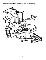
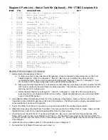
Diagram 8 Parts List – Water Tank Kit (Optional) – P/N 177855 Complete Kit
ITEM P/N DESCRIPTION QTY
1 177855 Water Tank Kit (Complete-Includes Items 2 – 24) 1
2 177778 Water Tank Bracket 1
3 174648 Water Tank (w/ Cap), 7 Gallon 1
3a 178863 Cap, Water Tank, 7 Gallon 1
4 020742 Washer, Flat .313 Dia 4
5 020785 Lockwasher, Split .312 Dia 4
6 197227 Capscrew, Hex Hd M8 x 1.25 x 20mm 2
7 166673 Clamp, Vinyl Coated 1/4 Hole x 5/8 ID 3
8 139722B Hose, 3/8 ID (139722 Bulk Qty In Inches = 8.5) 1
9 020049 Hose Clamp, Worm Drive 3
10 139761 Capscrew, Hex Hd M6 x 1.0 x 20mm 3
11 177813 Water Outlet Bracket 1
12 020766 Washer, Flat .500 SAE 2
13 030654 Adapter, 1/4 NPT x 3/8 Barb 1
14 020875 Bushing, Hex 1/4 NPT Male x 1/8 NPT Female 1
15 020811 Fitting, Elbow, Street 1/8 NPT x 90 Degree 1
16 048902 Nozzle, 1/8 NPT 1
17 139722A Hose, 3/8 ID (139722 Bulk Qty In Inches = 25) 1
18 020784 Lockwasher, Split .250 Dia 1
19 167478 Capscrew, Hex Hd M8 x 1.25 x 25mm 2
20 174016 Fitting, Hose Barb 3/8 ID x 3/4 Male 1
21 174741 Kit: Quick Disconnect Garden Hose w/Valve 1
22 174020 Fitting, Hose Barb 3/8 ID x 3/4 Female 1
23 040254 Washer, Hose 1
24 139745 Locknut, Fiber M6 x 1.0 2
Assembly of Kit (Use Diagram 8 for reference):
1. Before starting the assembly of this kit:
a) To improve access to the underside of the gearbox, it may be required to temporarily remove the Front
Shield (Diagram 1- Item 18 or Diagram 2 - Item 28). Be sure to re-install this item when this kit is
completely installed. Do Not remove the Dust Port Weldment (Diagram 1- Item 19, or Diagram 2 – Item
29), even if it must be temporarily held in place with its attaching hardware.
b) Make sure that the Valve (Item 21) is assembled so that when the valve halves are disconnected, the ON /
OFF lever is located on the water tank side of the assembly. This will allow removal of the tank from the
machine, even if it contains water.
c) Rotate the Dust Shield Cover (Diagram 1 – Item 20, or Diagram 2 – Item 30) to the open position by
loosening the two (2) Capscrews that hold it in position. Tighten the hardware to secure the Dust Shield
Cover in the OPEN position.
2. Assemble the Water Outlet Bracket (Item 11) to the underside of the gearbox. Remove the two (2) existing
Capscrews located under the gearbox at the front of the machine. The fittings could be already assembled, but if
not assemble them as shown in Diagram 8.
3. Secure the Water Tank (Item 3) in position by using the Bracket (Item 2) and attaching hardware.
4. Attach the Hose (Item 8) to the Water Tank (Item 3) and secure the Hose Clamp (Item 9). Again, make sure that
the Water Valve (Item 21) is properly assembled (Per Note 1b shown above).
5. Route the Hoses (Item 8 & Item 17) as shown in Diagram 8. Be sure to route the hose through the side of the
frame, and through the open Dust Shield Cover (Step 1c). Put the Hose Clamp (Item 9) onto the Hose (Item 17),
and then push the hose over the end of the Hose Adapter (Item 13). Securely tighten the Clamp onto the barb end
of the Adapter.
6. Install the Vinyl Hose Clamps (Item 7) in the positions shown in Diagram 8.
7. Re-install the Front Shield if it was removed in step 1a.
Summary of Contents for DT11H
Page 7: ...7...
Page 8: ...8...
Page 9: ...9...
Page 10: ...10...
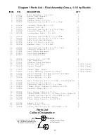
Page 28: ...28 Diagram 1 Final Assembly Group 1 5 hp Electric...
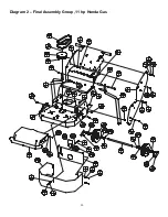
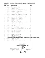
Page 30: ...30 Diagram 2 Final Assembly Group 11 hp Honda Gas...
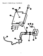
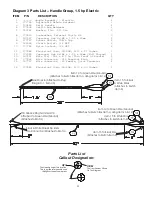
Page 32: ...32 Diagram 3 Handle Group 1 5 hp Electric...
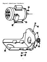
Page 36: ...36 Diagram 5 Motor Group 1 5 hp Electric...
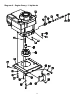
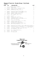
Page 38: ...38 Diagram 6 Engine Group 11 hp Honda...
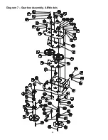
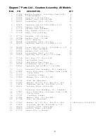
Page 40: ...40 Diagram 7 Gearbox Assembly All Models...
Page 42: ...42 Diagram 8 Water Tank Kit Optional P N 177855 Complete Kit...
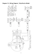
Page 50: ...50 Diagram 15 Wiring Diagram 1 5hp Electric Model...

