15
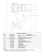
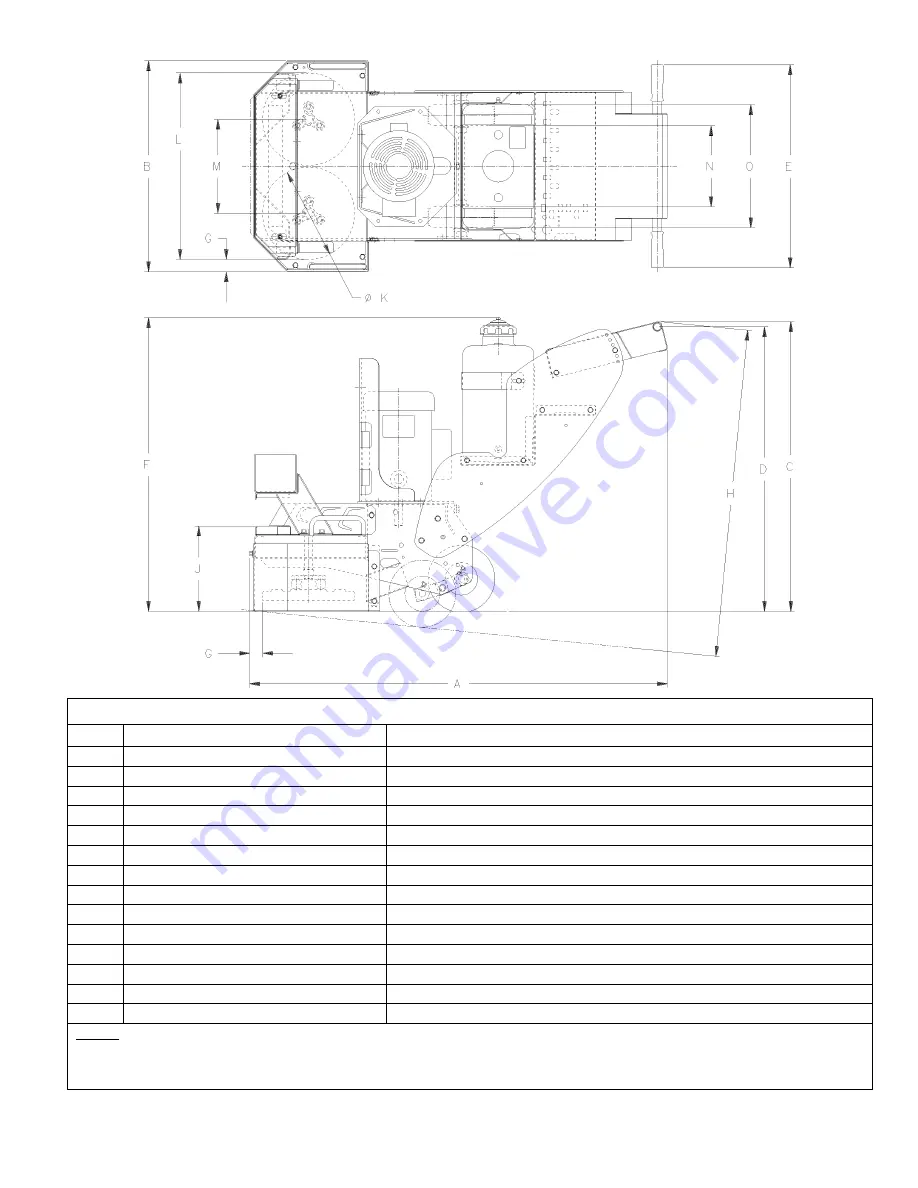
(DT15_dims.tif)
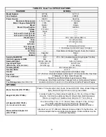
Dimensions (Note 1)
Item
Length (cm)
Description
A
50.2” (127.5)
Length – Maximum (With Handle In Low Position)
B 25.12”
(63.8)
Width
C
37.6” (95.5)
Operating Height (Maximum – Note 1)
D
37.0” (94.0) – 31.5” (80.0)
Handle Height (Maximum – Minimum)
E
24.2” (61.5)
Handle Width
F
35.0” (88.9)
Water Tank Height
G
1.50” (3.8)
Grind To Wall (Front and Side)
H
41.9 (106.5)
Transport Height (Maximum – Note 2)
J
10.2” (25.8)
Front Height
K
11.0” (27.9)
Disk Diameter
L
22.2 (56.4)
Grinding Width
M
11.200 (28.45)
Spindle Center Distance
N
9.6” (24.4)
Width Inside Tires
O
14.6” (37.0)
Width Outside Tires
Notes:
1. Dimensions are for the machine with the axle in “operation” position unless otherwise specified.
2. Dimension “H” is for the machine with the axle in “Transport” position.
Summary of Contents for DT11H
Page 7: ...7...
Page 8: ...8...
Page 9: ...9...
Page 10: ...10...
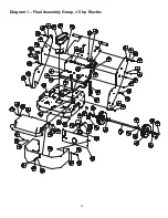
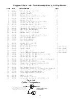
Page 28: ...28 Diagram 1 Final Assembly Group 1 5 hp Electric...
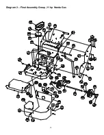
Page 30: ...30 Diagram 2 Final Assembly Group 11 hp Honda Gas...
Page 32: ...32 Diagram 3 Handle Group 1 5 hp Electric...
Page 36: ...36 Diagram 5 Motor Group 1 5 hp Electric...
Page 38: ...38 Diagram 6 Engine Group 11 hp Honda...
Page 40: ...40 Diagram 7 Gearbox Assembly All Models...
Page 42: ...42 Diagram 8 Water Tank Kit Optional P N 177855 Complete Kit...
Page 50: ...50 Diagram 15 Wiring Diagram 1 5hp Electric Model...


