20
protection will not protect the operator from an
electrical shock due to improper grounding
practice, frayed or cracked extension cords, or
other defective electrical components. This
exposure to electrical shock increases greatly
whenever the equipment is used around water or
other conductive fluids. The operator will be
provided with electrical shock protection whenever
the machine is connected to a circuit that has a
Ground Fault Circuit Breaker. The Ground Fault
Circuit Breaker will open the circuit whenever it
senses a fault current, greater than a few
milliamps, in the ground path. If a receptacle with a
Ground Fault Circuit Breaker is not available, a
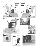
Portable Ground Fault Circuit Interrupter [MM] [See
FIG. 7] can be used at the branch receptacle to
provide the same level of protection.
Gasoline Model:
Engine Fuel: Check the engine operation manual.
Unleaded gasoline is recommended.
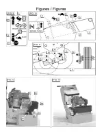
Engine Oil: Put the AXLE in the OPERATION
POSITION [F] [See FIG. 11] so that the engine is in
a horizontal position, then, check that the engine oil
level is correct. Check the oil level frequently to
ensure that the level never falls below that
specified in the engine operation manual. If the oil
level is low, add SAE 10W30, service classification
SF or SG oil (for normal conditions) as
recommended in the engine operation manual. DO
NOT overfill engine with oil!
Before starting the engine verify that the Throttle
Lever [L] is between the START [N] and STOP [M]
position. This will allow the engine to be started
while the clutch is disengaged. NOTE: The engine
clutch will engage at 1800 RPM, and the Accessory
Disks [P] will begin to rotate.
Before starting the engine, verify that the engine
does NOT exceed 20 degrees angle of inclination
when the unit is in operation.
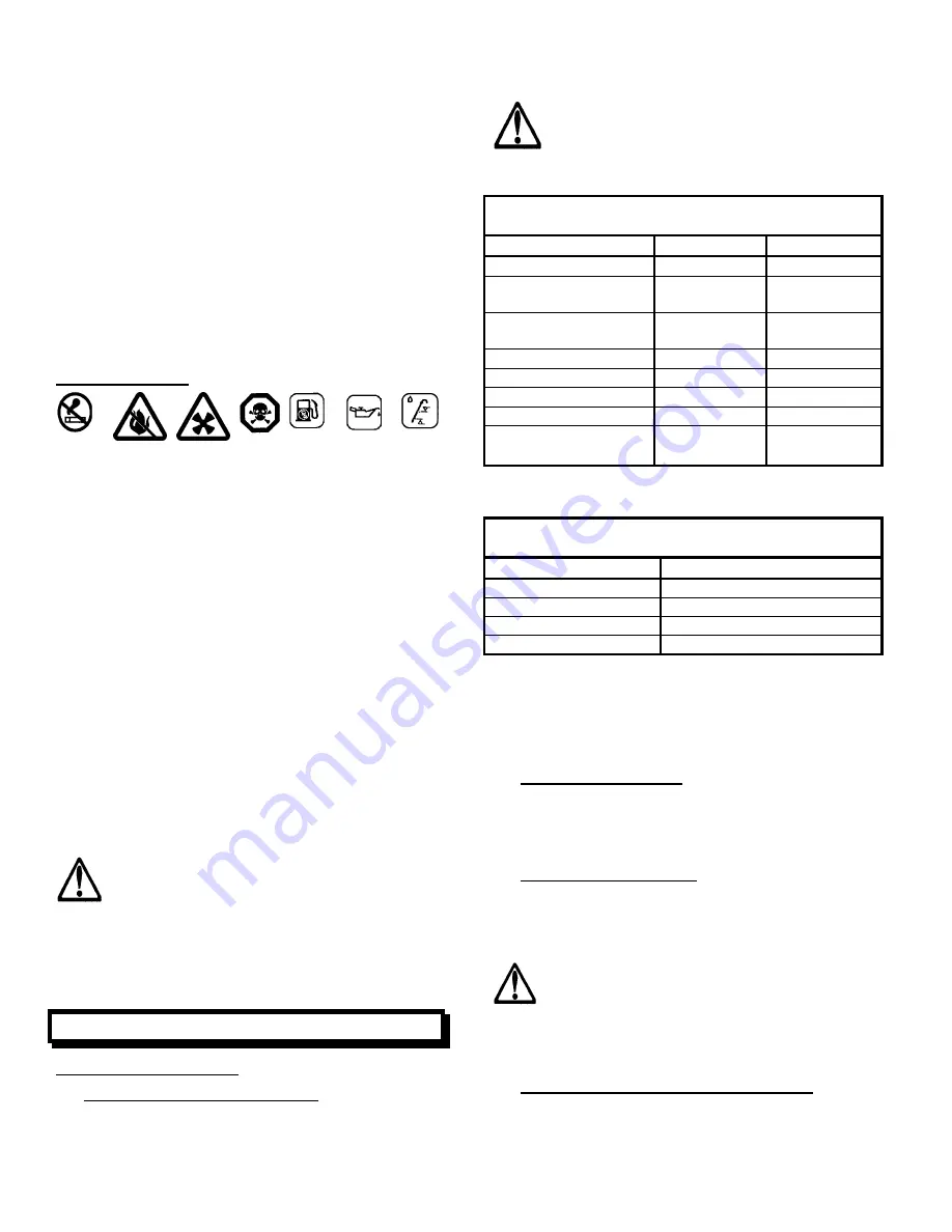
WARNING:
Run the machine only if the
grinding heads are on the ground. Raising the
front of the machine with the engine or motor
running could cause injury or death to by-
standers or the operator. Also, engine
inclination angles greater than 20 degrees
could cause severe engine damage and void
your engine warranty!
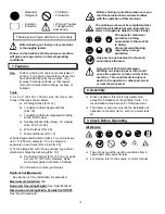
4. Tool Installation
TOOL INSTALLATION:
1) Rear Axle Position (See FIG. 11): Make sure the
Axle is in the Transport Position [E]. Using TABLE
3 (below) install the Axle Stop Bolts [G] in the
proper position for the tool being mounted. The
Axle Stop Bolts [G] are factory installed in the F2
position.
Table 3 shows the tools specified by our
company. Tools from other manufactures
may fit onto this machine. Measure “Tool
Height” to determine the proper axle position
(See TABLE 4) for these tools.
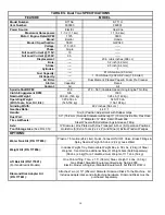
TABLE 3
Rear Axle Positions (See FIG. 11)
Tool
Tool Height
Axle Position
Grinding Stones
2.0” (51 mm)
F2
Tungsten Carbide
Block
2.1” (53 mm)
F2
Diamond Segment
Block
2.1” (53 mm)
F2
Star wheels
2.25” (57 mm)
F2
Beam Cutter Wheels
2.25” (57 mm)
F2
TC Wheels
2.15” (54 mm)
F2
Diamond Disks
2” (51 mm)
F2 or E2
Scrubbing Pad
(with Adapter)
1.7”
(43.2mm)
F3
If the tool to be installed is not listed in TABLE 3:
a) Measure the “Tool Height”.
TABLE 4
Tool Height for Axle Positions (See FIG. 1)
Axle Position
Minimum Tool Height
F1
2.44” (62 mm)
F2
2.00” (50.8 mm)
F3
1.69” (42.9 mm)
F4
1.00” (25.4 mm)
b) Using TABLE 4, find a “Minimum Tool Height”
equal to, or greater than, the measured tool height.
c) Referencing FIG. 11, install and tighten the Axle
Stop Bolts [G] in the Axle Position (F1, F2, etc)
determined from step b) above.
2) Raise Front Shield (A): Loosen the three (3)
Capscrews [B] that hold the Front Shield [A] in
position. Raise the Front Shield to its upper
position, then tighten the Capscrews [B] to hold it in
place.
3) Tilt Machine Backwards: When on a flat surface,
tilt the machine backward until the Handles [FF]
rest on the ground. If you are not sure the machine
will stay in this position, add a weight or other
device to the handle to secure them to the ground.
WARNING: Make sure the machine is stable
when the front end is raised into the air!
Secure the machine in this position if you are
not sure about its stability. Secure machine
BEFORE starting attachment of the tools to
the accessory disks!
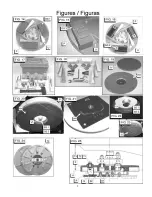
4) Tool Installation on Accessory Disk [P]:
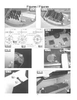
See FIG. 14, FIG. 15, FIG. 16, FIG. 26, FIG. 27
a) Place
the
Tool [GG 1] so that it rests against the
back and outside of the tool holding area of the
Summary of Contents for DT11H
Page 7: ...7...
Page 8: ...8...
Page 9: ...9...
Page 10: ...10...
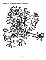
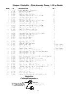
Page 28: ...28 Diagram 1 Final Assembly Group 1 5 hp Electric...
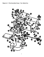
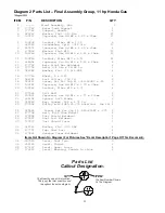
Page 30: ...30 Diagram 2 Final Assembly Group 11 hp Honda Gas...
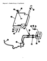
Page 32: ...32 Diagram 3 Handle Group 1 5 hp Electric...
Page 36: ...36 Diagram 5 Motor Group 1 5 hp Electric...
Page 38: ...38 Diagram 6 Engine Group 11 hp Honda...
Page 40: ...40 Diagram 7 Gearbox Assembly All Models...
Page 42: ...42 Diagram 8 Water Tank Kit Optional P N 177855 Complete Kit...
Page 50: ...50 Diagram 15 Wiring Diagram 1 5hp Electric Model...

