T&R 228-1 Operating And Maintenance Manual Download Page 1


OPERATING AND MAINTENANCE MANUAL 


Product:


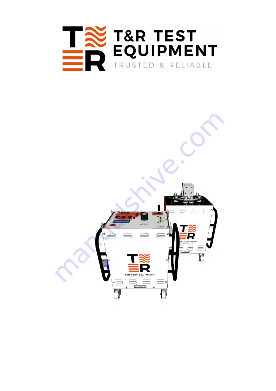
Primary Current Injection System 

Type: 

CU-Ps and PLU-5k or PLU-6k 


DESIGNED AND MANUFACTURED BY: 

T & R Test Equipment Limited 

15-16 Woodbridge Meadows, Guildford, Surrey, GU1 1BJ, United Kingdom 
Telephone:  01483 207428 

e-mail: 

[email protected] 

Web:  www.trtest.com 


Summary of Contents for 228-1

Page 1: ...ary Current Injection System Type CU Ps and PLU 5k or PLU 6k DESIGNED AND MANUFACTURED BY T R Test Equipment Limited 15 16 Woodbridge Meadows Guildford Surrey GU1 1BJ United Kingdom Telephone 01483 20...

Page 2: ...s information before making connections to any terminal It is ESSENTIAL to consult the product manual for rating information before making any connection to a terminal or terminal group marked with a...

Page 3: ...anual CAUTION This action or procedure may be dangerous if not carried out correctly and may cause damage to the equipment or connected equipment WARNING This action or procedure may cause injury or d...

Page 4: ......

Page 5: ...played Values and Messages 22 1 4 1 Displayed Values 22 1 4 2 Warning Messages 22 1 5 Primary Current Injection Lead Sets 24 1 5 1 Description 24 1 5 2 Factors Affecting Maximum Output Current 25 1 6...

Page 6: ...ay 41 3 1 1 Timer Mode 41 3 1 2 Connections 41 3 1 3 Test Procedure 41 3 2 Primary Injection of an Over Current Relay 42 3 2 1 Timer Mode 42 3 2 2 Connections 42 3 2 3 Test Procedure 42 3 2 4 Using Pu...

Page 7: ...Procedure 47 4 MAINTENANCE 49 4 1 Output Control Brushes 49 4 2 Removal of the CU Ps from Case 49 5 STANDARD ACCESSORIES 51 5 1 Spare Fuses Supplied 51 5 2 Standard Accessories Supplied 51 5 3 Option...

Page 8: ...8 7 REVISION 55...

Page 9: ...e rated at 12kVA for 1 second All metering is digital A memory facility is provided to hold the current reading when the output trips or is switched off The current is thyristor controlled and is auto...

Page 10: ...10 1 1 Control Unit Front Panel Layout and Functions Figure 1 1 CU Ps front panel layout R B C D E F G H I T S J N M L O K A P Q...

Page 11: ...Parallel indicator Illuminated when PLU is connected in parallel mode J Series indicator Illuminated when PLU is connected in series mode K Main output control Sets output current L Output ON and OFF...

Page 12: ...a range of optional loading units and output lead sets The loading unit is connected to the control unit using a metering cable and a power cable The load is connected between the terminals 1 5 and 4...

Page 13: ...s Used to connect terminals for Series and Parallel Modes C Series Mode Diagram Diagram to show how to connect Links for Series Mode D Output Terminals High current output to object under test E CU Ps...

Page 14: ...t current and therefore supply current may be higher for a maximum of two seconds In every case the maximum achievable output current is defined by the output cable and load impedance 1 3 2 Loading Un...

Page 15: ...ects whether the PLU loading unit is in Parallel or Series mode on the CU Ps control unit when The CU Ps is turned ON from the mains supply AND the ammeter select switch is in the main output range OR...

Page 16: ...000A 6000A Max kVA 40 40 40 40 open circuit voltage at 230V mains The main output from the CU Ps control unit is a 0 230V supply rated at 100A for 5 minutes on 15 minutes off This output is NOT isolat...

Page 17: ...cted using the metering range select switch Unit Range Voltage Current Continuous 5 min on 15 min off 1 min on 15 min off CU Ps 33A 15V 10A 20A 33A 100A 5V 33A 67A 100A The secondary injection output...

Page 18: ...connection Loading unit Metering range Metering full scale Accuracy Trip current PLU 5k 10 500 0A 0 5 rdg 5d 525A 50 2500A 0 5 rdg 5d 2625A 100 5000A 0 5 rdg 5d 5250A PLU 6k 10 600 0A 0 5 rdg 5d 630A...

Page 19: ...rent and auxiliary input or the ratio between output current and auxiliary current Two inputs are provided one for voltages up to 300V and the other for currents up to 5A The input in use is automatic...

Page 20: ...ut primary and auxiliary current input secondary CT ratio 1A 5000 1A Displays the ratio of a 1A CT connected between the current output primary and auxiliary current input secondary Phase 179 9 to 180...

Page 21: ...s 0 99999 9s 1ms 10ms 100ms 0 01 rdg 2d Single contact 0 01 rdg 2d Dual contact 0 01 rdg 2d Current operated 0 01 rdg 4d In current operated mode timing results obtained with test currents below 20 of...

Page 22: ...isplayed on screen 1 4 2 Warning Messages In addition to the normal display screens the CU Ps systems can display a range of warning messages if the unit trips on over current or duty cycle or is too...

Page 23: ...dary injection selected with loading unit power lead plugged in to CU Ps Connect Loading Unit OFF to continue Figure 1 4 6 Primary injection selected with loading unit not connected Press OFF to conti...

Page 24: ...on 1 minute off rating Cores strapped together Cores laid out flat Cores strapped together Cores strapped together 3000AL 1200A 3000A 1500A 6000A 4000AL 1400A 4000A 2000A 8000A 5000AL 1600A 5000A 250...

Page 25: ...impedance The lead impedance is often dominant in defining the maximum current that may be injected into the load The cross sectional area of the leads and the lead layout have a large effect on impe...

Page 26: ...Auxiliary metering current input F6 3A fuse 1 7 Construction The CU Ps control unit is housed in a robust steel case with castors for mobility The front panel is protected by a steel cover which is f...

Page 27: ...on the side of the unit is connected to a low impedance local earth This is essential if the unit is used in a sub station environment WARNING Ensure that the unit is adequately earthed If necessary a...

Page 28: ...een the CU Ps and loading unit are shown in figure 2 1 Figure 2 1 CU Ps and loading unit connections WARNING It is vital to ensure that secure low impedance connections are made between the output of...

Page 29: ...connections Configure the loading unit for either parallel or series output depending on the voltage and test current required Ensure that all the nuts are fully tightened See figure 1 3 1 for connec...

Page 30: ...imiting the current Output leads too long Use shorter output leads Output leads in a large loop minimising the area in the loop of the output leads will maximise the current available Output leads of...

Page 31: ...e secondary injection metering ranges selected Figure 2 2 Secondary Injection Connections 2 2 1 Connections Ensure that the unit is switched off and the test object is isolated and grounded before mak...

Page 32: ...ent Switch the output on using the ON push button and then increase the output current to the desired test current 2 2 3 After Testing On completion of the test switch off the output using the OFF pus...

Page 33: ...tact 1 C1 1st change C1 2nd change C1 1st change timer start Auto recloser Single Contact using Contact 2 C2 1st change C2 2nd change C2 2nd change timer stop Drop off timing Dual Contact 1st change C...

Page 34: ...e timer starts on the first change of state of contact set 1 after the output is switched on and stops on the second change on contact set 1 The output is automatically switched off when the timer is...

Page 35: ...trips are set to double the normal trip current in the 0 2s 0 5s and 1s pulse modes In the 2s pulse mode the trips function as normal This is useful for setting the current when testing thermal device...

Page 36: ...thermal breakers it will be necessary to use the current operated timer mode When the output ON push button is pressed the following will occur a The timer will start and current will flow through th...

Page 37: ...3 Entering a comment Each result is tagged with a comment when it is stored The comment is entered by setting the store result control to COMMENT and typing the comment using the optional USB keyboard...

Page 38: ...timer mode to internal start and press the OFF button for the main output when a result is to be stored Results are not stored when the timer is set to OFF This allows the output current to be set wi...

Page 39: ...time date and time between samples in ms 0 06 60 s The second line specifies column headings and subsequent lines list one sample value for main output current in A and one sample value for the auxili...

Page 40: ......

Page 41: ...1 2 Connections Connect the relay current coil to the most appropriate output on the CU Ps 5V 100A or 15V 33A Connect the trip contacts on relay under test to contact set 1 on the CU Ps 3 1 3 Test Pr...

Page 42: ...output from loading unit to desired input on device under test Connect trip contact on the relay under test to contact set 1 on the control unit 3 2 3 Test Procedure Switch on the main supply switch S...

Page 43: ...nt output from loading unit to desired input on device under test Connect the trip contact on the relay under test to contact set 1 on the control unit 3 3 3 Test Procedure Switch on the main supply s...

Page 44: ...in supply switch Set timer mode switch to the off position Ensure that the output control is in the zero position Check that connections are made as figure 3 4 Press output ON push button and adjust o...

Page 45: ...to closed or vice versa The timer will stop when the contacts return to their original state 3 6 Using the Control Unit as a Dual Contact Timer 3 6 1 Timer Mode Dual contact 3 6 2 Connections Connect...

Page 46: ...to COM input 3 7 3 Test Procedure Switch on the main supply switch Set timer mode switch to the off position Ensure that the output control is in the zero position Check that connections are made as f...

Page 47: ...Ps auxiliary metering input S1 S2 3 8 3 Test Procedure Switch on the main supply switch Set timer mode switch to the off position Ensure that the output control is in the zero position Check that conn...

Page 48: ......

Page 49: ...ld be examined and replaced if necessary The interval between inspection and renewal of the brushes will depend upon the amount of usage particularly at very high currents However it should be remembe...

Page 50: ......

Page 51: ...ect the PLU loading unit to CU Ps control unit A204 0003 5 metre test lead set for timing tests between contacts and CU Ps control unit S000 0534 5 metre 100A lead set for use with the secondary injec...

Page 52: ......

Page 53: ...outputs 1 5kV RMS for 1 minute 6 3 Accuracy of Instruments 6 3 1 Loading Unit Current Output Loading unit Metering range Metering full scale Accuracy Trip current PLU 5k Parallel Mode 10 500 0A 0 5 r...

Page 54: ...00 0V 0 7 rdg 5d 5 000A RMS 5 000A 0 7 rdg 5d 6 3 4 Timing System Timer mode Range Resolution Accuracy Internal start 0 999 999s 9999 99s 99999 9s 1ms 10ms 100ms 0 01 rdg 2d Single contact 0 999 999s...

Page 55: ...REVISION Product Type Primary Current Injection CU Ps PLU Loading Units File CU Ps manual v1 doc Author G Bond Date 17 06 19 Issue Date 1 20 08 19 Modified By M Clancy Checked By N Eldridge Date 28 1...

Page 56: ...56 Drawings Required A3 002121 latest issue CU Ps A3 002135 latest issue PLU 5k A3 002127 latest issue PLU 6k...

Reviews: